Difference between revisions of "Edit/en"
(Updating to match new version of source page) |
(No difference)
|
Latest revision as of 12:08, 14 May 2018
Contents
Structure
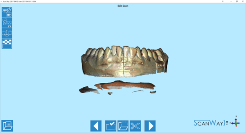
After each scanning step, except for the articulator, the wizard interface presents the Image Edit step. For this step, the lower toolbar adapts offering a selection of tools and actions.
Another edit step is the identification of markers and dies (when scanned using the custom setup and not the multi-die).
Edit Toolbar
 Previous
- Goes back to the previous step. Icon not active during the first scanning step.
 Selection Tools
- Opens the selection tool panel in which it is possible to choose how to select part of the image. The available tools will be described later in this page.
 Select Action
- Opens the actions panel in which it is possible to choose what to do with the selected part of the image. The available actions will be described later in this page.
 Cut base
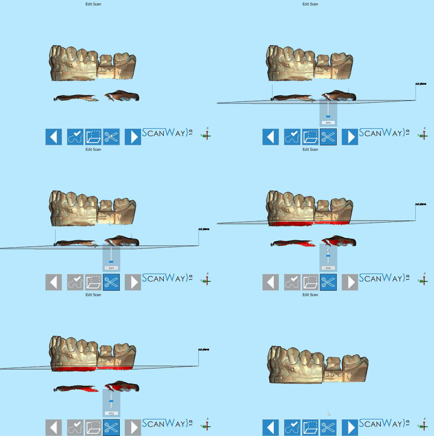
- Cuts the base of the object with a straight plane. This tool will be described in detail later in this page.
 Next
Next- Goes one step forward in the project. This icon is available when the ongoing step is complete or in steps that can be skipped.
Selection Tools
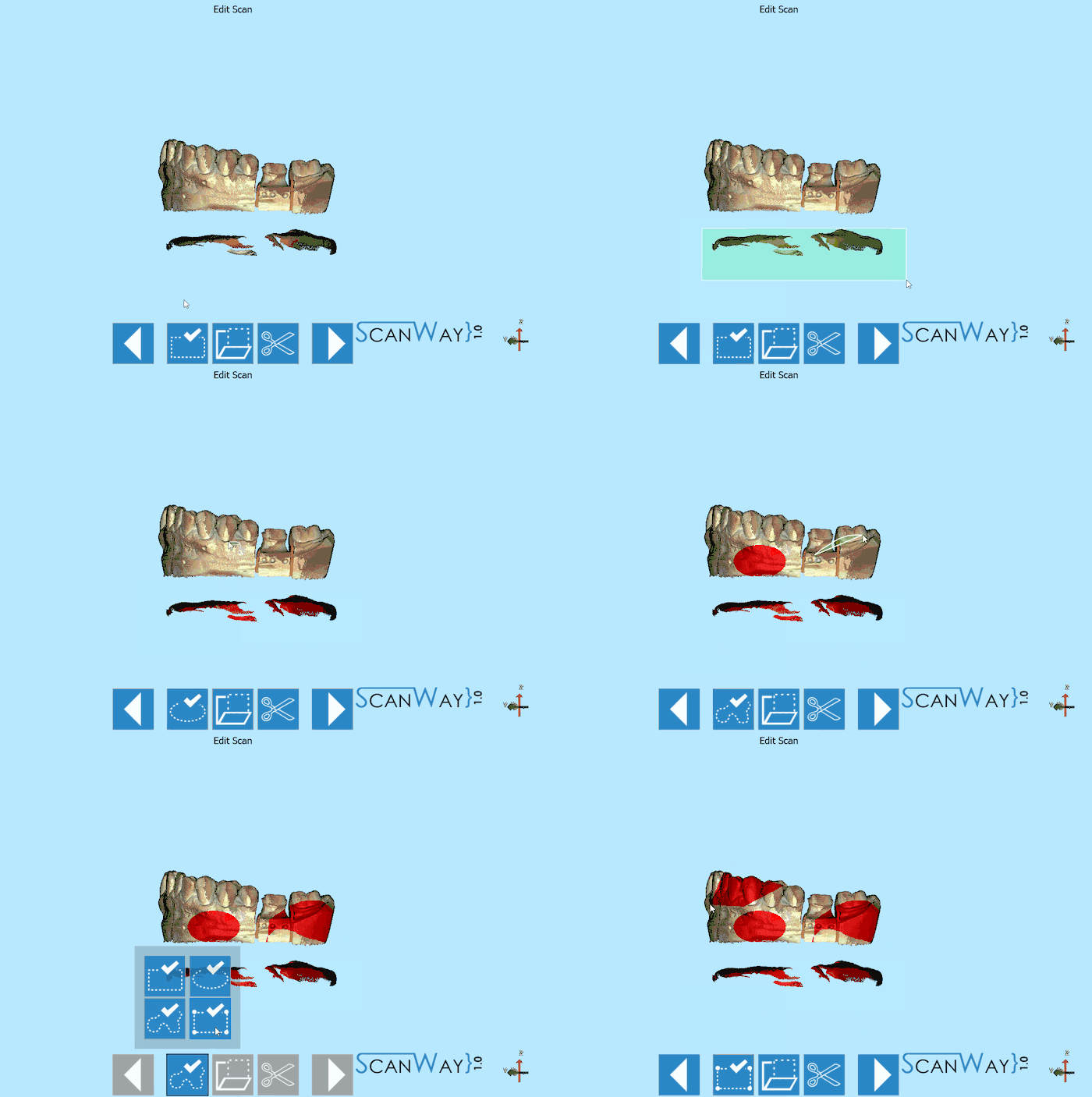
As shown in the GIF, these tools allow selecting part of the image to edit the object. Four selection tools are available:
 Rectangular Selection
- Draws a rectangle that starts from the click point and grows following the mouse; to select, release the left mouse button.
 Elliptical Selection
- Draws an ellipse centered in the click point that grows following the mouse; to select, release the left mouse button.
 Free Closed Line Selection
- Click and hold the left mouse button to start drawing a line that follows the mouse. Release the left mouse button to close the line and select all the area inside its borders.
 Polygonal Selection
- Click in two different points to draw a line and a third point to create a polygon. Double click to close the polygon and select all the area inside its borders
Actions
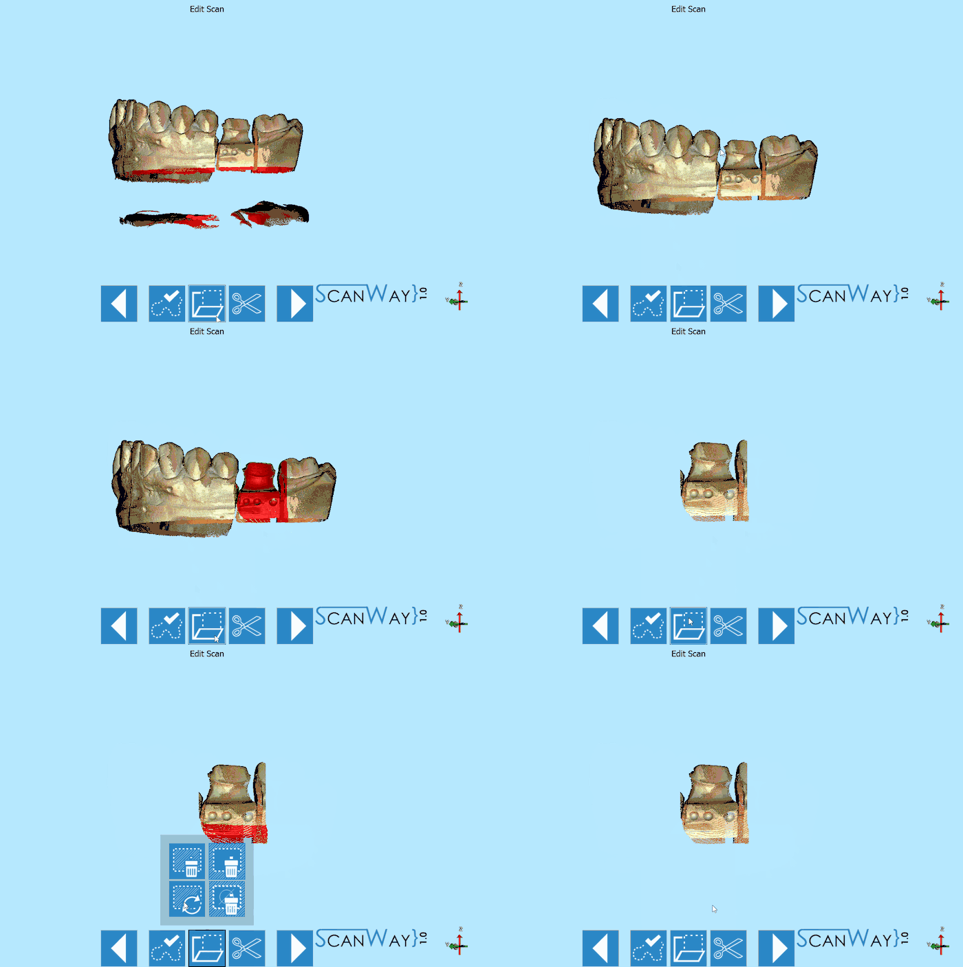
These actions allow to modify the selected information. The following actions are available:
 Delete Selection (DEL)
 - Deletes the currently selected data.
 Crop Selection (
 + K)
+ K) - Keeps only the selected data and removes all the rest.
 Invert Selection (
 + I)
+ I) - Selects all the data that is not selected and deselects the selected data.
 Clear Selection (
 + C)
+ C) - Deselects all the data.
Cut Base
To use the Base Cut tool, click on the ![]() button then, either click on the model or drag the cursor to determine the height of the cut. Click Apply to accept the changes. Here below an explanatory video.
button then, either click on the model or drag the cursor to determine the height of the cut. Click Apply to accept the changes. Here below an explanatory video.
Dies identification
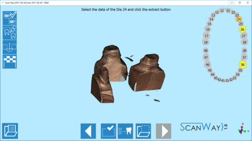
When scanning dies using the custom setup, as shown in the Scan Interface page, the dies need to be identified.
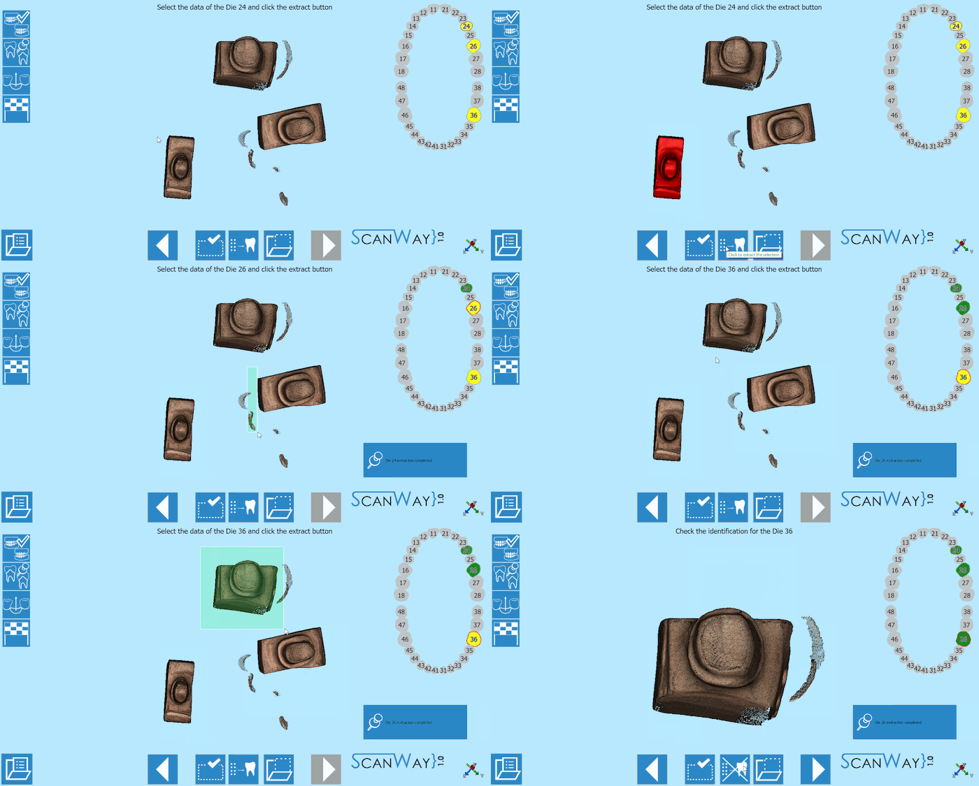
The interface shows a specific main toolbar, a teeth graphic on the right showing the elements that need to be identified. Before the identification the dies are marked in yellow, the item marked with the red border is the one that needs to be identified and separated from the others. The wizard will underline all the items in an established sequence, the user can select manually the item to be identified by left clicking on its number in the teeth graph.
The main toolbar offers these tools:
 Previous
- Goes back to the previous step. Icon not active during the first scanning step.
 Selection Tools
- Opens the selection tool panel in which it is possible to choose how to select part of the image. The available tools will be described later in this page.
 Extraction
- Extracts the image of the selected die from the general scan, thus identifying and separating it from the others.
 Select Action
- Opens the actions panel in which it is possible to choose what to do with the selected part of the image. The available actions will be described later in this page.
 Next
Next- Goes forward one step in the project. This option is not available until all the items have been identified and separated.
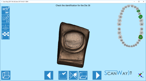
Once the items have been identified and separated, they are marked in green in the graph. In case an error occurs during identification and two or more stumps get mixed up, it is possible to restart the identification by clicking on one of the ![]() icon.
icon.
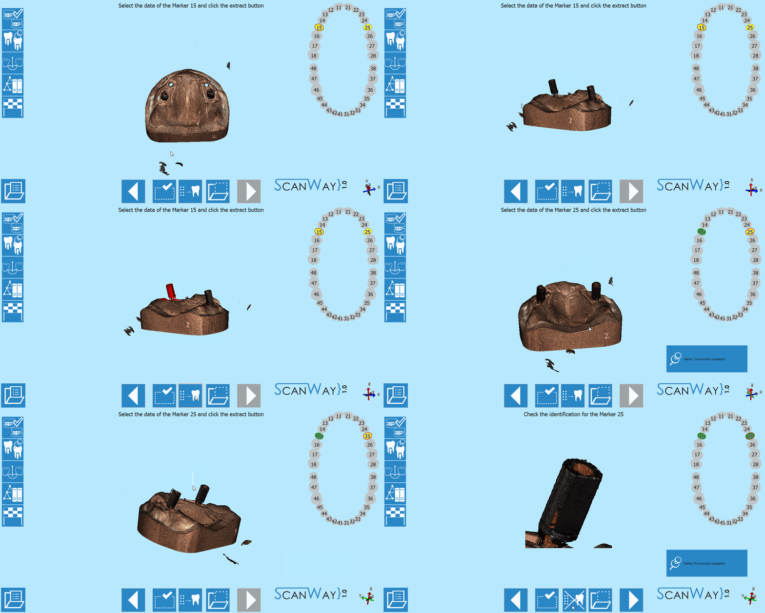
Marker identification
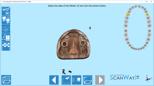
When scanning implant cases, the user needs to use markers as reference for the position of the implant. Once scanned, each marker needs to be identified and separated from the others.
The interface shows a specific main toolbar, a teeth graphic on the right showing the elements that need to be identified. Before the identification the teeth are marked in yellow, the item marked with the red border is the one that needs to be identified and separated from the others. The wizard will underline all the items in an established sequence, the user can select manually the item to be identified by left clicking on its number in the teeth graph.
The main toolbar offers these tools:
 Previous
- Goes back to the previous step. Icon not active during the first scanning step.
 Selection Tools
- Opens the selection tool panel in which it is possible to choose how to select part of the image. The available tools will be described later in this page.
 Extraction
- Extracts the image of the selected die from the general scan, thus identifying and separating it from the others.
 Select Action
- Opens the actions panel in which it is possible to choose what to do with the selected part of the image. The available actions will be described later in this page.
 Next
Next- Goes forward one step in the project. This option is not available until all the items have been identified an separated.
Once the items have been identified and separated, they are marked in green in the graph. In case an error occurs during identification and two or more markers get mixed up, it is possible to restart the identification by clicking on one of the ![]() icon.
icon.
