Difference between revisions of "Edit/it"
(Created page with "Quando si scansionano i monconi con il setup personalizzato, come mostrato nella pagina Interfaccia di Scansione, tali monconi vanno identificati.") |
(Created page with "L'interfaccia mostra una specifica barra degli strumenti principale, un grafico dei denti sulla destra che mostra gli elementi che devono essere identificati. Prima di essere...") |
||
| Line 50: | Line 50: | ||
{{Screenshot|segment-interface-dies.png}} | {{Screenshot|segment-interface-dies.png}} | ||
| − | + | L'interfaccia mostra una specifica barra degli strumenti principale, un grafico dei denti sulla destra che mostra gli elementi che devono essere identificati. Prima di essere identificati i monconi sono di colore giallo; l'elemento marcato con un bordo rosso è quello che deve essere identificato e separato dagli altri. La Modalità Guidata porterà ad identificare tutti gli elementi in una sequenza stabilita; l'utente può selezionare manualmente l'elemento da identificare facendo click con il tasto sinistro sul corrispondente numero nel grafico dei denti. | |
The main toolbar offers these tools: | The main toolbar offers these tools: | ||
Revision as of 07:11, 22 May 2017
Contents
Struttura
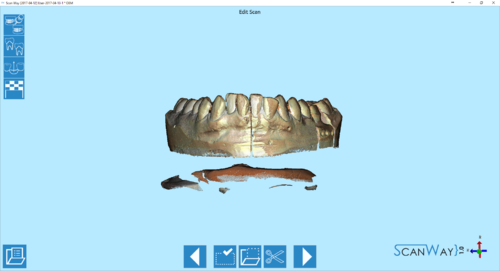
Dopo ciascun passaggio di scansione, escluso quello per l'articolatore, l'interfaccia della Modalità Guidata presenta il Passaggio di Modifica dell'Immagine. Per ciascun passaggio, la barra degli strumenti in basso si adatta offrendo una selezione di strumenti ed azioni.
Un altro passaggio di modifica è l'identificazione dei marker e dei monconi (quando scansionati utilizzando il setup personalizzato e non il multi die).
Barra degli Strumenti Modifica
 Precedente
- Torna al passaggio precedente. Icona non attiva durante la prima scansione.
 Strumenti di selezione
- Apre il pannello dello strumento di selezione in cui è possibile scegliere come selezionare parte dell'immagine. Gli strumenti disponibili saranno descritti più avanti in questa pagina.
 Azione di Selezione
- Apre il pannello di azioni in cui è possibile scegliere cosa fare con la parte selezionata dell'immagine. Le azioni disponibili saranno descritte più avanti in questa pagina.
 Tagliare la Base
- Taglia la base dell'oggetto con un piano diritto. Questo strumento sarà descritto più avanti in questa pagina.
 Successivo
- Prosegue di un passaggio nel progetto. Questa icona è disponibile quando il passaggio in corso è completo o in passaggi che possono essere tralasciati.
Strumenti di Selezione
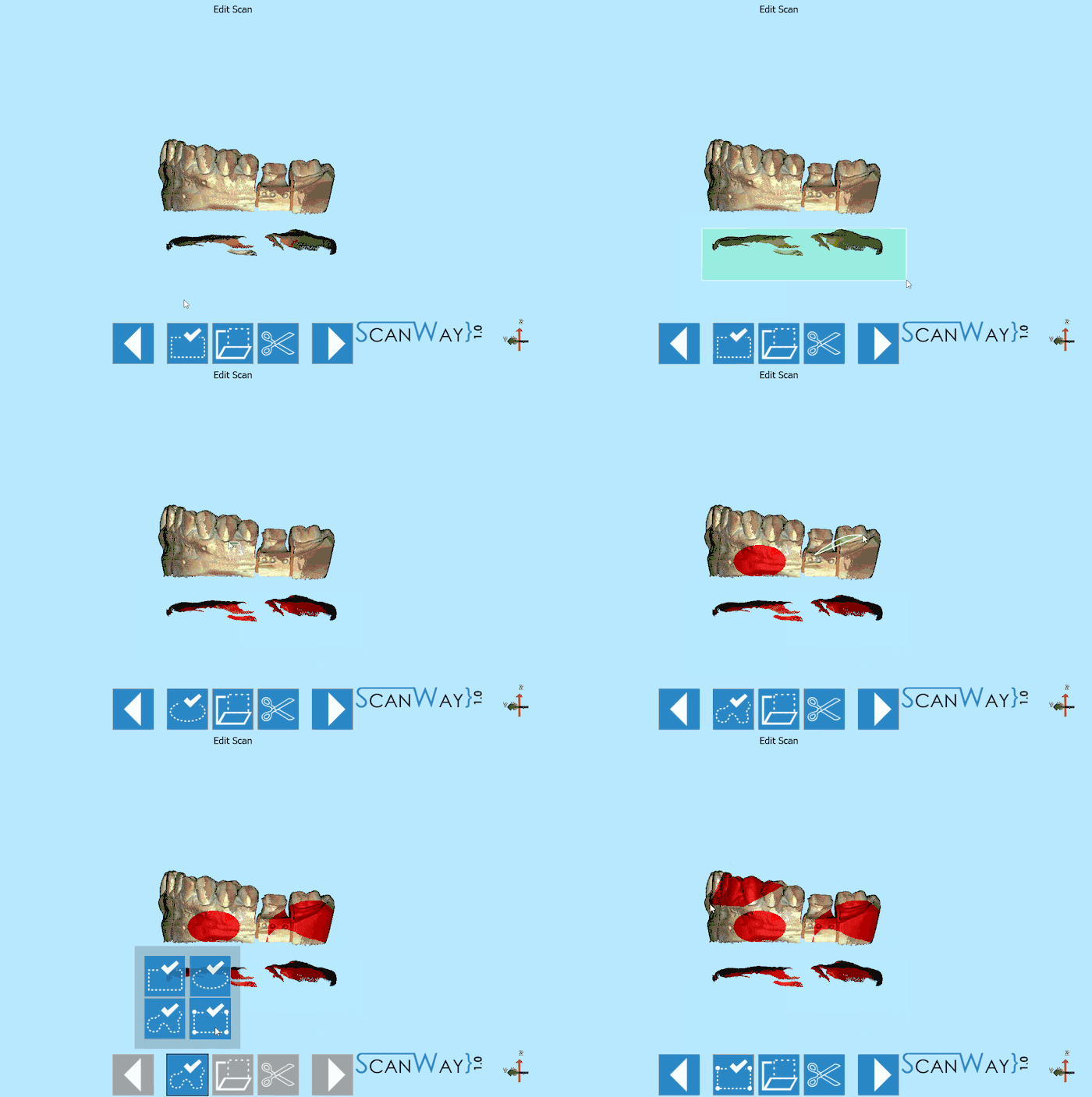
Come mostrato nella GIF, questi strumenti permettono di selezionare parte dell'immagine per modificare l'oggetto. Sono disponibili quattro strumenti di selezione:
 Selezione Rettangolare
- Disegna un rettangolo che parte dal punto in cui si fa click e aumenta seguendo il mouse; per selezionarlo, rilasciare il bottone sinistro del mouse.
 Selezione Ellittica
- Disegna un'ellisse centrata nel punto in cui si fa click e che aumenta seguendo il mouse; per selezionarlo, rilasciare il bottone sinistro del mouse.
 Selezione con Linea Chiusa Libera
- Fare click e tenere il tasto sinistro del mouse per iniziare a disegnare una linea che segue il mouse. Rilasciare il tasto sinistro del mouse per chiudere la linea e selezionare tutta l'area all'interno dei suoi confini.
 Selezione Poligonale
- Fare click in due punti differenti per disegnare una linea, e fare un terzo punto per creare un poligono. Doppio click per chiudere il poligono e selezionare tutta l'area all'interno dei suoi confini.
Azioni
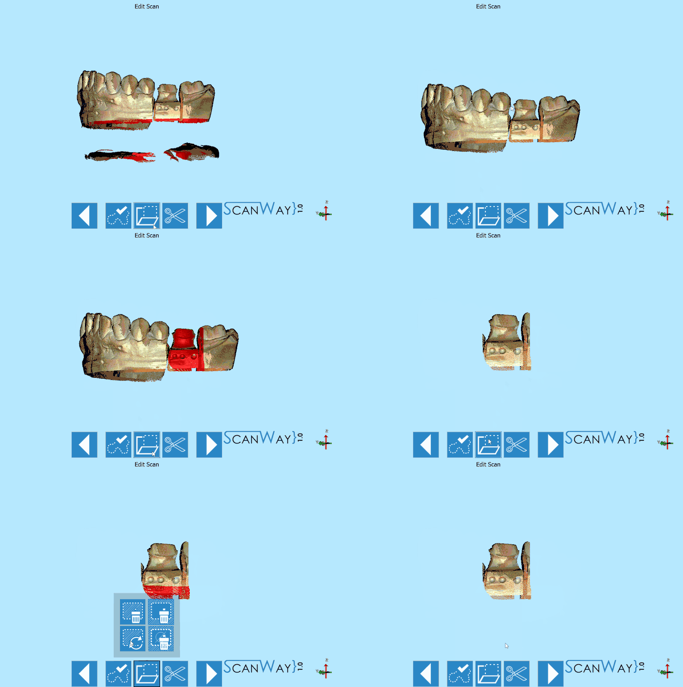
Queste azioni permettono di modificare le informazioni selezionate. Sono disponibili le seguenti azioni:
 Selezione Cancella (CANC)
 - Cancella i dati selezionati.
 Selezione Taglio(
 + K)
+ K) - Mantiene solo i dati selezionati e rimuove tutto il resto.
 Selezione Inverti (
 + I)
+ I) - Seleziona tutti i dati che non sono selezionati e de-seleziona i dati selezionati.
 Cancella Selezione (
 + C)
+ C) - Deseleziona tutti i dati.
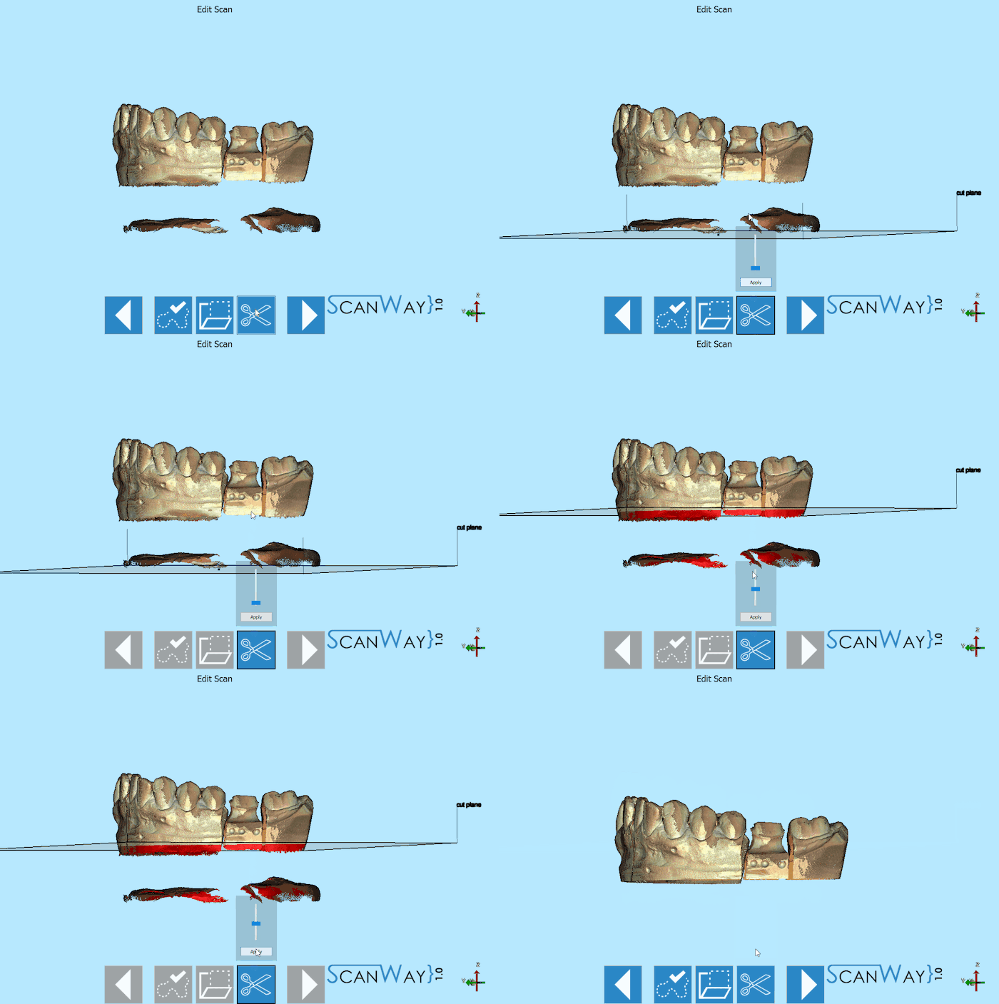
Tagliare la Base
Per usare lo strumento Tagliare la Base, fare click sul bottone ![]() , poi fare click sul modello o spostare il cursore per determinare l'altezza del taglio. Fare click su Conferma per confermare le modifiche. Di seguito un video di spiegazione.
, poi fare click sul modello o spostare il cursore per determinare l'altezza del taglio. Fare click su Conferma per confermare le modifiche. Di seguito un video di spiegazione.
Identificazione dei Monconi
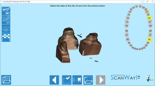
Quando si scansionano i monconi con il setup personalizzato, come mostrato nella pagina Interfaccia di Scansione, tali monconi vanno identificati.
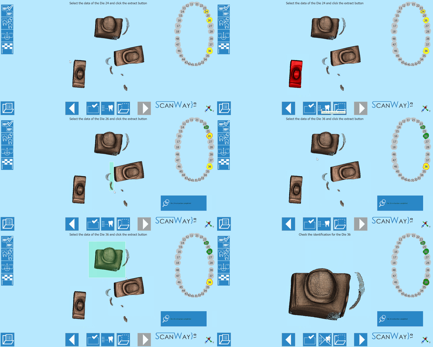
L'interfaccia mostra una specifica barra degli strumenti principale, un grafico dei denti sulla destra che mostra gli elementi che devono essere identificati. Prima di essere identificati i monconi sono di colore giallo; l'elemento marcato con un bordo rosso è quello che deve essere identificato e separato dagli altri. La Modalità Guidata porterà ad identificare tutti gli elementi in una sequenza stabilita; l'utente può selezionare manualmente l'elemento da identificare facendo click con il tasto sinistro sul corrispondente numero nel grafico dei denti.
The main toolbar offers these tools:
 Previous
- Goes back to the previous step. Icon not active during the first scanning step.
 Selection Tools
- Opens the selection tool panel in which it is possible to choose how to select part of the image. The available tools will be described later in this page.
 Extraction
- Extracts the image of the selected die from the general scan, thus identifying and separating it from the others.
 Select Action
- Opens the actions panel in which it is possible to choose what to do with the selected part of the image. The available actions will be described later in this page.
 Next
Next- Goes forward one step in the project. This option is not available untill all the items have been identified an separated.
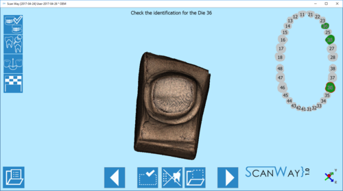
Once the items have been identified and separated, they are marked in green in the graph. In case an error occurs during identification and two or more stumps get mixed up, it is possible to restart the identification by clikcing on one of the ![]() icon.
icon.
Marker identification
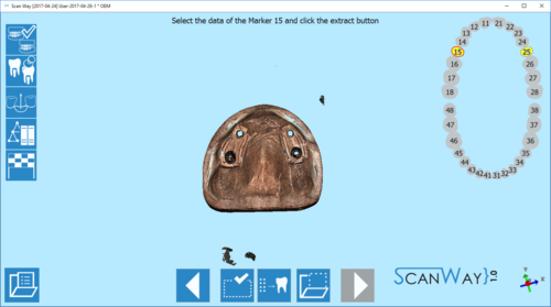
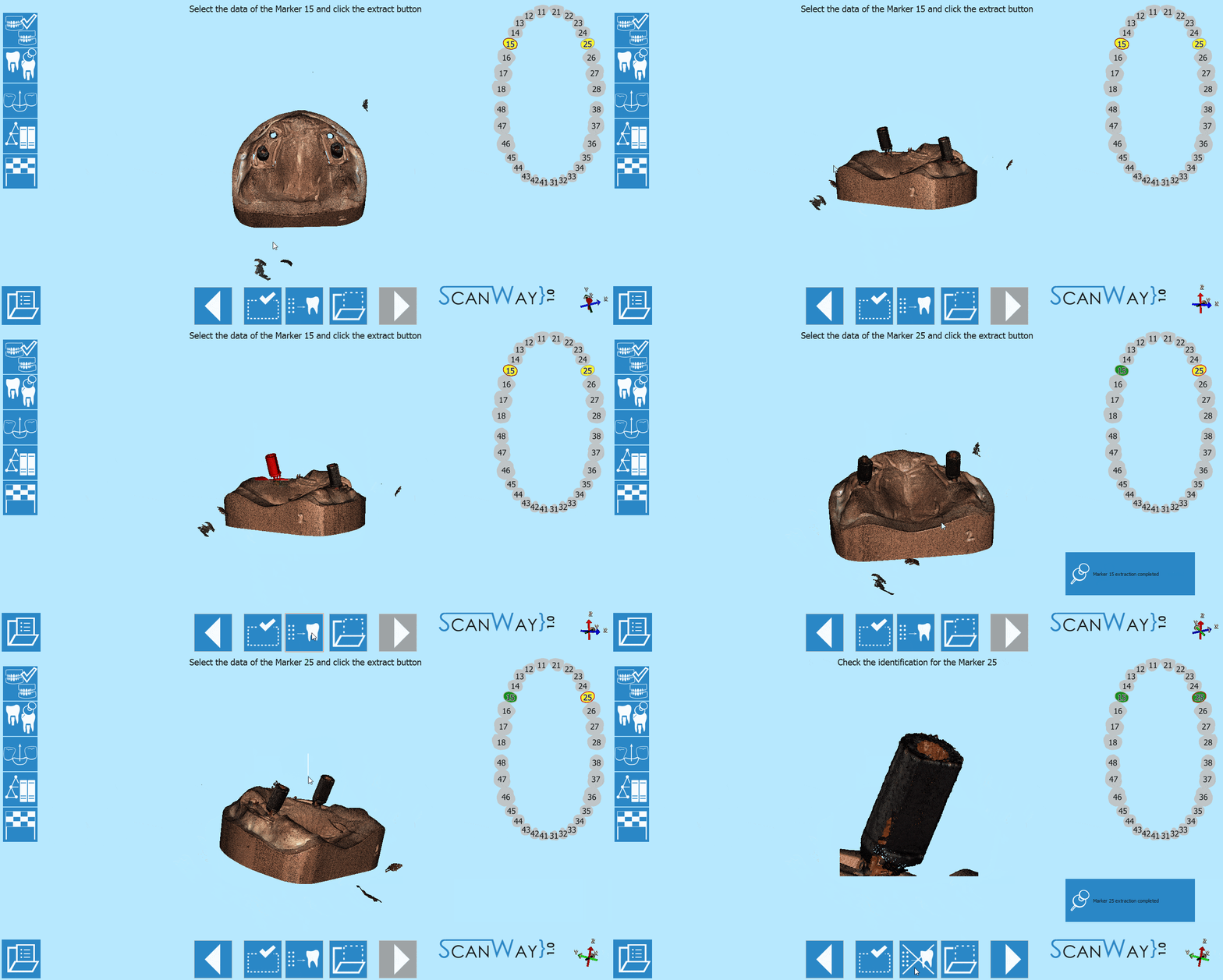
When scanning implant cases, the user needs to use markers as reference for the position of the implant. Once scanned, each marker needs to be identified and separated from the others.
The interface shows, a specific main toolbar, a teeth graphic on the right showing the elements that need to be identified. Before the identification the teeth are marked in yellow, the item marked with the red boder is the one that needs to be identified and separated from the others. The wizard will underline all the items in an established sequence, the user can select manually the item to be identified by left clicking on its number in the teeth graph.
The main toolbar offers these tools:
 Previous
- Goes back to the previous step. Icon not active during the first scanning step.
 Selection Tools
- Opens the selection tool panel in which it is possible to choose how to select part of the image. The available tools will be described later in this page.
 Extraction
- Extracts the image of the selected die from the general scan, thus identifying and separating it from the others.
 Select Action
- Opens the actions panel in which it is possible to choose what to do with the selected part of the image. The available actions will be described later in this page.
 Next
Next- Goes forward one step in the project. This option is not available untill all the items have been identified an separated.
Once the items have been identified and separated, they are marked in green in the graph. In case an error occurs during identification and two or more markers get mixed up, it is possible to restart the identification by clikcing on one of the ![]() icon.
icon.
