Alignment Interface
General Alignment
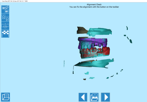
The alignment is an intermediate step that often goes unnoticed since it is almost always automatic. In fact, when the automatic alignment succeeds, the user will only see an alignment check window.
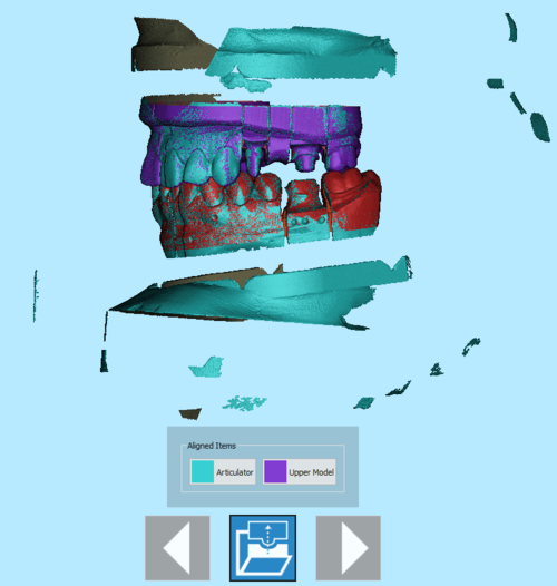
The alignment check window shows all the aligned items in different colors and a specific toolbar:
 Previous
- Goes back to the previous step. Icon not active during the first scanning step.
 Fix Alingment
- Shows a list of the aligned items to allow the user to fix one of them, should it be incorrect.
 Next
Next- Goes forward one step in the project. This option is not available until all the items have been identified and separated.
When clicking on the ![]() button, the aligned items list is shown.
button, the aligned items list is shown.
By clicking on one of the aligned items, the manual alignment panel opens to allow the user to fix the automatically performed alignment.
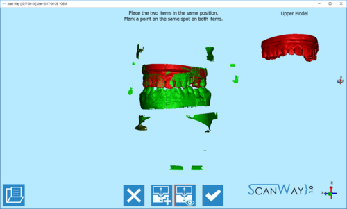
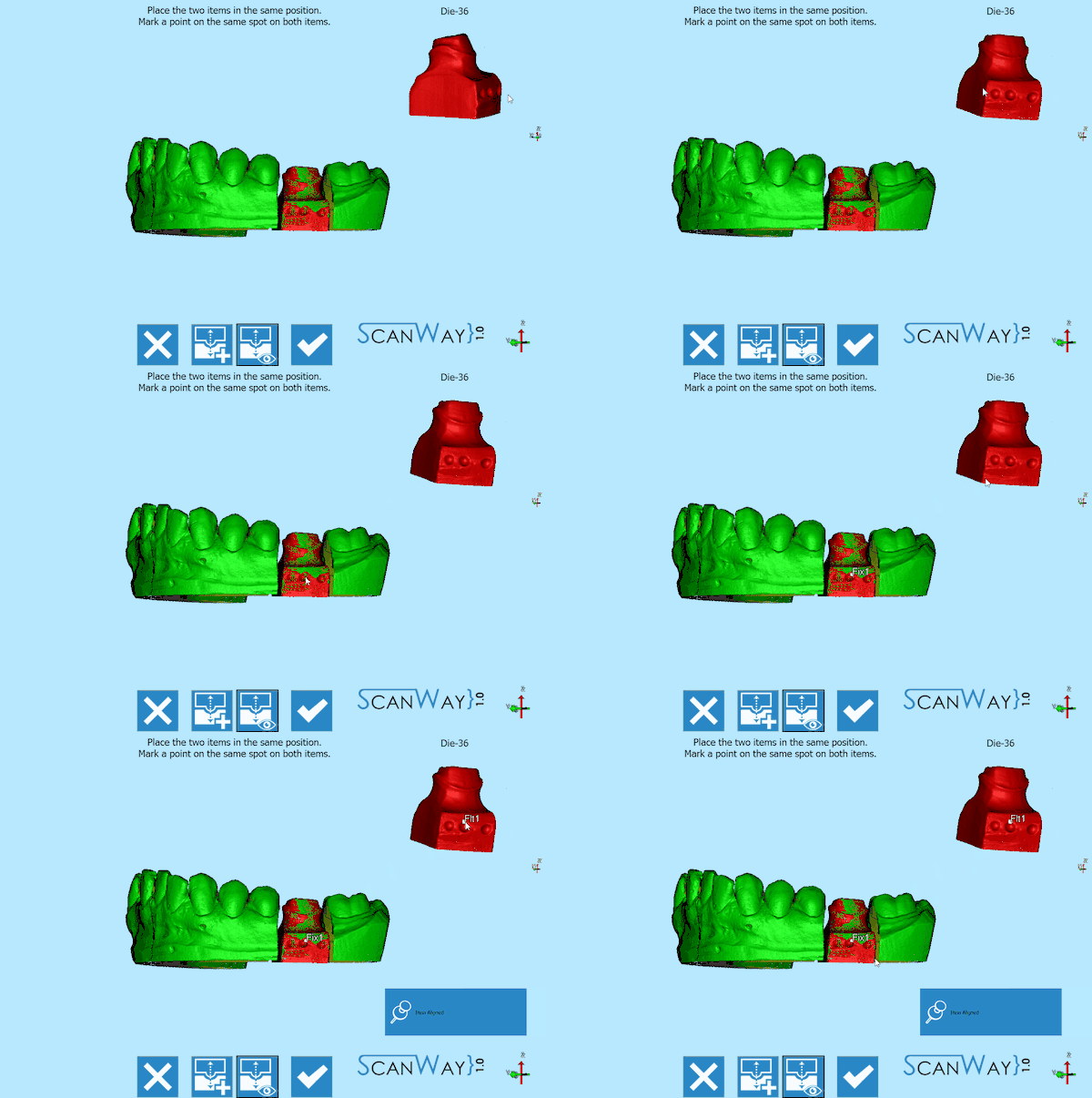
In the manual alignment step are shown, in the center of the window, the fixed or reference element to which the detailed item will be aligned; in the upper right corner, the floating or moving item that will be matched with the reference; a specific toolbar.
 Exit
Exit- Exits the Options section.
 Best Fit
- Fixes the alignment between the two images. This action is usually automatic.
 View Floating
- Shows or hides the image of the floating/ moving item.
 Big Panel
- Shows the floating item in a bigger panel.
 Accept
- Accepts the changes and closes the option section.
To perform the alignment, put the two images (fixed and moving) in the same position and mark one point on the same spot of both items. If necessary, due to difficult matches or lack of information, it is possible to place multiple points on the images.
Accept or cancel the changes to continue with the project.
Implant Markers
When acquiring the data for a project on implants, acquiring the implant itself is problematic. It's not like a stump or a piece of stone model. The implant connections/interfaces are normally small and metallic.
Moreover, the fitting has to be mechanically perfect, with no margin of error.
To solve this problem, the implant connection is not directly scanned but a Implant Marker or Scan Body is used instead. A Scan Body is a specific object, designed to be scanned, which fits exactly over the implant.
The scan of the implant marker itself is not enough: its resulting data will be used to compute the exact position of the implant interface. In order to carry out this operation, an Implant Library is needed.
The alignment to the implant library can be performed in the CAD software. However, using an implant library for Exocad's Platform, the user can perform this operation directly in the scanning software ScanWay, in order to get better results.
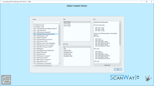
Library Selection
The implant library selection is automatically shown when all the items of the project have been acquired.
The Panel is divided into 4 Sections:
- Library
- For choosing the general connection and implant family, contains:
- A Filter box where it is possible to write part of the name of the needed implant. All the implants that match the name will be showed in the implant list
- An implant list with all the implants available in the current Implant Library
- Type and Sub Type
- For Choosing the diameter and type of connection. There can be many of these types, in our libraries, for instance, there are:
- Engaging Connections : the connection can not rotate on the implant, suggested for abutments or single restorations
- Not-Engaging Connections : the connection can rotate on the implant, suggested for bars and bridges
- For Zirconia : connections with specific shapes, suited for zirconia restorations
- Preview
- Shows the preview of the STL marker present in the library
- Info
- If the library is correctly configured to work with our software, in this section it is possible to have a small overview of the libraries with additional information on the available diameters and implant types.
All our libraries are provided with this feature and, being connected to this wiki, the Open in browser button opens the wiki on the implant list page.
To accept the implant selection click on Select, otherwise Cancel.
If the CAD design is launched using a wrong connection it will be necessary to restart all the design from the beginning
Marker Alignment
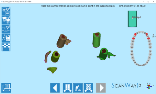
Once the library has been selected, the wizard shows the marker alignment step.
The interface shows all the acquired markers; an image of the STL of the library with a premarked point; a teeth graphic showing the elements that need to be aligned; a specific toolbar.
The toolbar offers this options:
 Previous
- Goes back to the previous step. Icon not active during the first scanning step.
 Change implant library
 - Allows to change implant library, for instance, if in one case have been used different connections.
 Show model
 - Shows or hides the reference model underneath the markers.
 Reset
Reset- Restarts the alignment from the beginning.
 Next
Next- Goes forward one step in the project. This option is not available until all the items have been aligned.
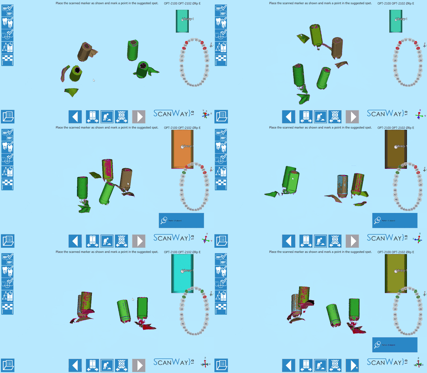
To align it is simply necessary to move the scanned markers to mimic the position of the library STL shown in the upper right corner of the window. When the marker is in the correct position, mark one point as suggested in the library image. Repeat for all the acquired elements, not necessarily following any order.
