Difference between revisions of "ExamplesFree/en"
(Updating to match new version of source page) |
(No difference)
|
Latest revision as of 15:30, 1 June 2018
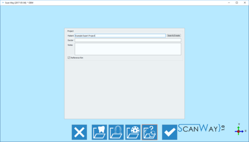
In this page will be explained how to scan a project in Expert mode. This kind of project has no wizard, so the only information required for creating the project is the general information section.
As no information has been provided, in this project there are no fixed steps, the user can scan any object in any order.
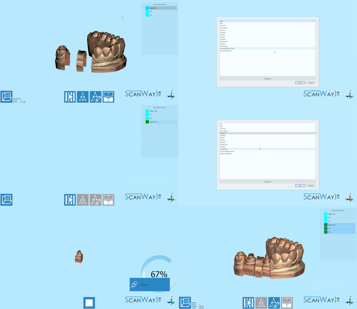
In this demo project, an upper jaw, and two dies have been scanned, aligned and meshed.
It is not necessary to follow the order of operations of this demo; still, it is suggested to align the items before meshing them
Upper Jaw
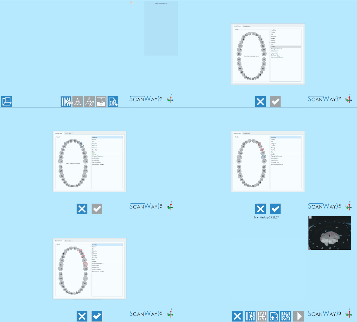
To start scanning click on the Scan Button![]() . Since there are no indications on the object to be scanned, the software will ask the user to select a scanning profile and, if needed, some advanced options. To learn more on the advanced parameters, go to the Scan Interface page -paragraph Advanced parameters.
. Since there are no indications on the object to be scanned, the software will ask the user to select a scanning profile and, if needed, some advanced options. To learn more on the advanced parameters, go to the Scan Interface page -paragraph Advanced parameters.
Here is our scan definition:
Once the profile has been selected the upper model scan can be started.
Place the model on the model holder and click the Scan Button![]() . Once the scan is finished the result will be shown.
. Once the scan is finished the result will be shown.
Also in the Expert project, the steps are divided into different moments, by clicking the next button ![]() the edit mode activates.
the edit mode activates.
Edit or trim the model using the available tools and click next. For detailed information on all the available options in this step visit the Edit Tools page.
To start another scan, click on the Scan button![]() .
.
Dies
In the Expert project, it is not possible to use the multi-die, since the software doesn't know which items will be scanned. Therefore the dies can be scanned in any possible way and combination. In our demo project, we have two dies, and we'll proceed to scan them both on the model holder.
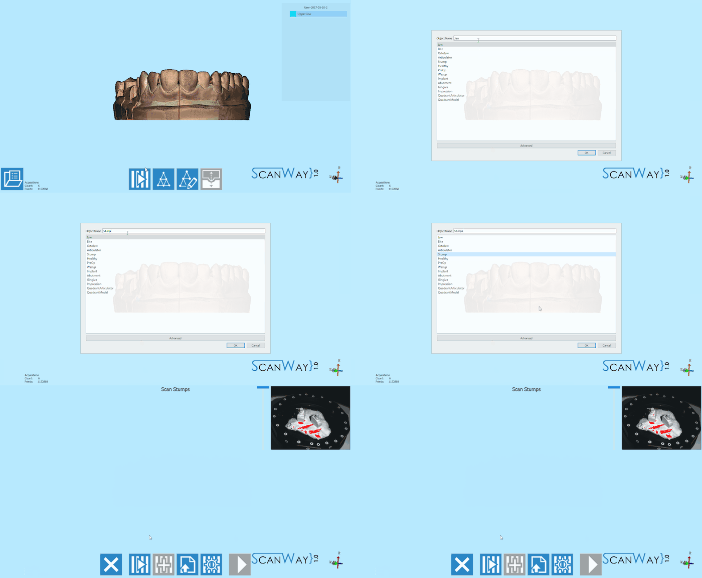
To start the scan, the profile needs to be selected:
At this point, the scan can be started. Place the dies on the chosen support and click the Scan Button![]() . Once the scan is finished the result will be shown.
. Once the scan is finished the result will be shown.
As for the previous item, by clicking ![]() the edit mode activates.
the edit mode activates.
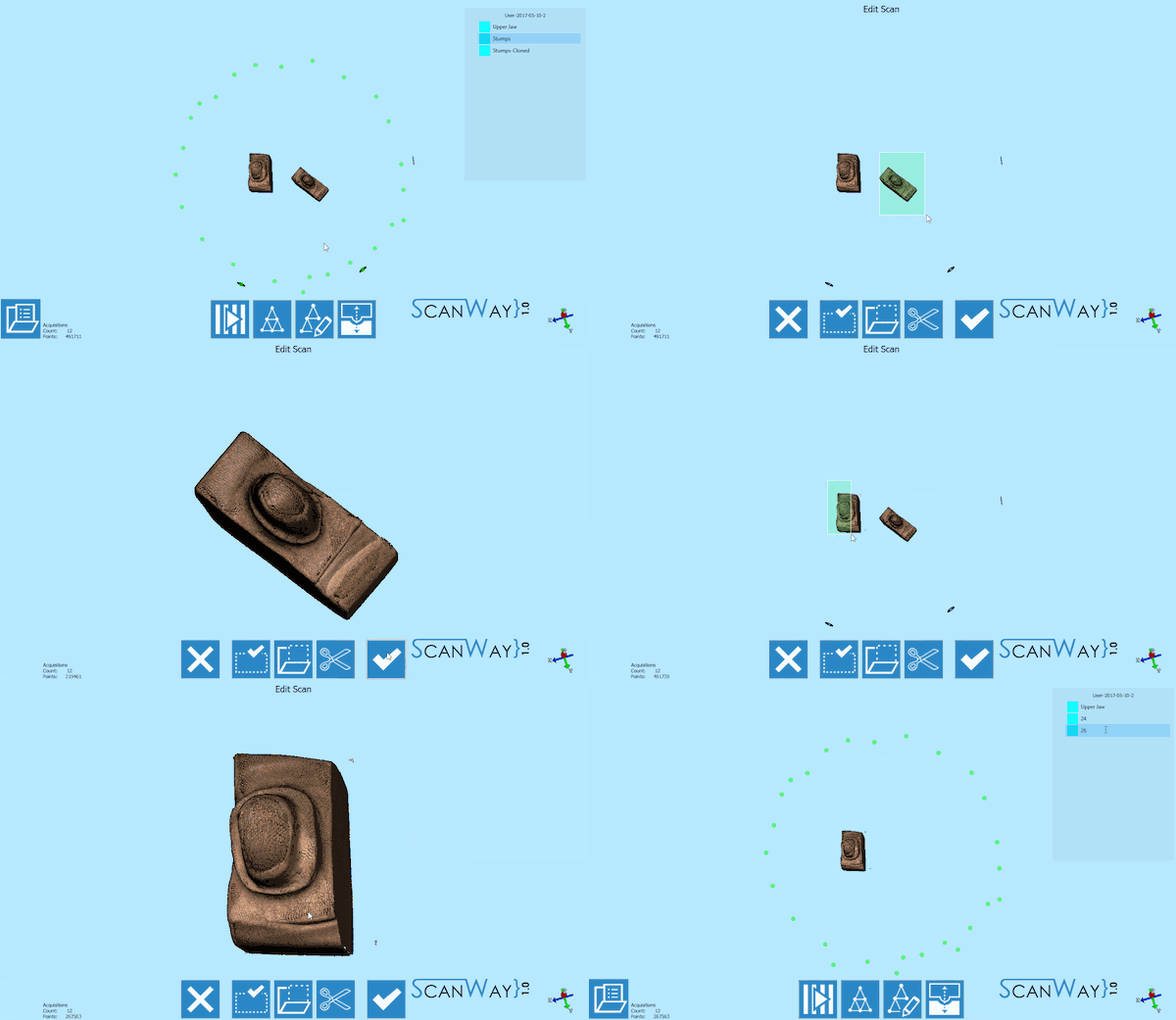
Two dies have been scanned together and are therefore saved in the same image. To be able to use them in a design project it is needed to separate the two items and create two different images.
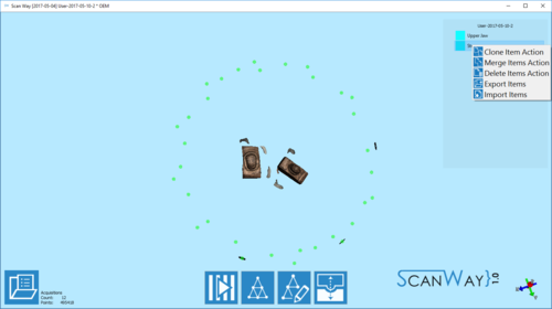
To do so, right-click on the Stump image in the items' list and click Clone Item Action.
Now edit and rename the two images, leaving only one element per image.
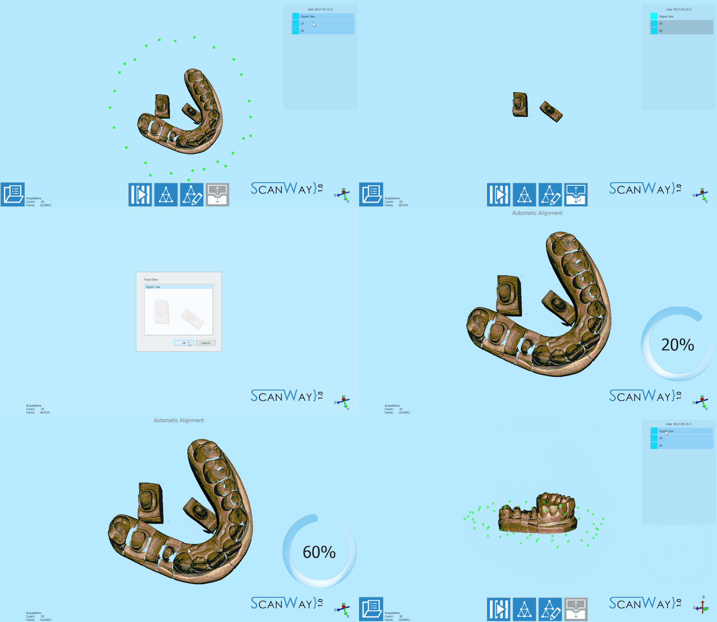
When all the items are in separate images, they can be aligned to their reference.
Alignment
Since this project doesn't have a structure, the software cannot start the alignment automatically. The user needs to select the items to align and their reference.
All the items are now in position and the user can start editing the images for mesh generation.
Reference Editing
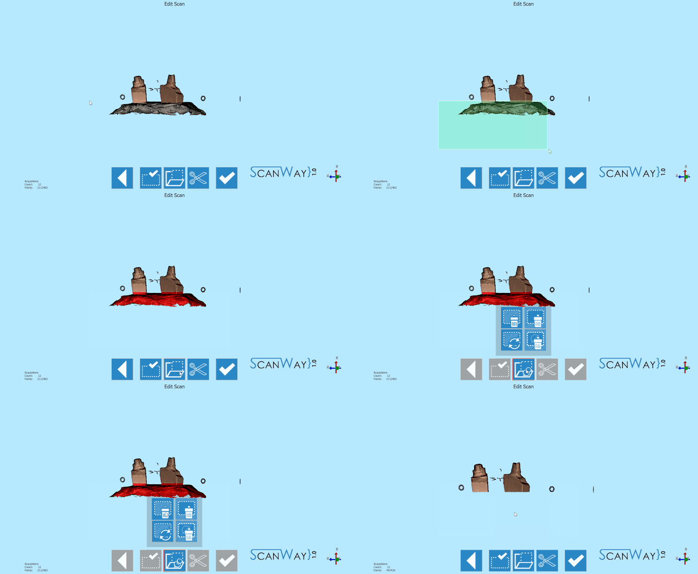
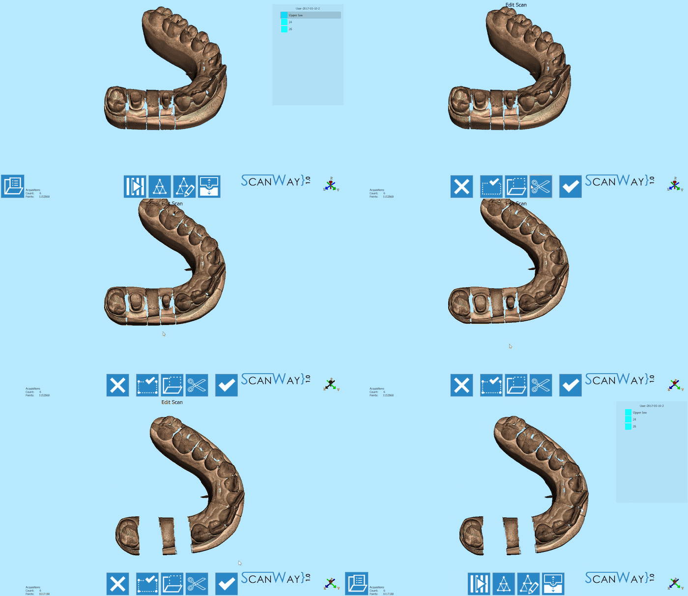
The reference editing is very important because it avoids exporting double surfaces to the CAD and consequential errors during design.
In Structured projects this step is completely automatic.
To delete double surfaces, click on the reference image (in this case the upper model) in the items' list and edit out the parts that were scanned separately.
Once all reference images have been edited the mesh can be generated.
Mesh Generation
As for the scans, different items get meshed in different ways. The user has to select a meshing profile for each item.
To then Export the generated meshes, right click on the meshed elements in the items' list and select Export Items. The software will ask the user to select the folder for the export.
