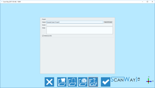
Example: Expert Project
In questa pagina si spiega come scansionare un progetto in Modalità Esperto. Questo tipo di progetto non ha una procedura guidata, pertanto l'unica informazione necessaria per creare il progetto è la sezione informazioni generali.
Poiché non sono state fornite nessune informazioni, in questo progetto non ci sono passaggi obbligatori, l'utente può scansionare qualsiasi oggetto in qualsivoglia ordine.
In questo progetto demo si è scansionato, allineato e generato mesh di un'arcata superiore e due monconi.
Non è necessario seguire l'ordine delle operazioni di questa demo; ma comunque si suggerisce di allineare gli elementi prima di generarne la mesh
Contents
Arcata Superiore
Per iniziare a scansionare cliccare sul Pulsante Scansiona . Dato che non vi sono indicazioni sull'oggetto da scansionare, il software chiedere all'utente di selezionare un profilo di acquisizione e, se necessario, altre opzioni avanzate. Per saperne di più sui parametri avanzati, visitare la pagina Scan Interface - paragrafo parametri Avanzati.
Di seguito la nostra definizione della scansione:
Una volta selezionato il profilo, si può avviare la scansione del modello superiore.
Posizionare il modello sul piattello e cliccare il Pulsante Scansiona . I risultati dell'acquisizione verranno mostrati sullo schermo.
Anche nel progetto in Modalità Esperto i passaggi sono suddivisi in vari momenti, facendo click sul bottone Successivo si attiva la modalità Modifica.
Modificare o tagliare il modello utilizzando gli strumenti disponibili e fare click su Successivo. Per informazioni dettagliate su tutte le opzioni disponibili in questo passaggio visitare la pagina Edit Tools.
Dies
In the Expert project it is not possible to use the multidie, since the software doesn't know which items will be scanned. Therefore the dies can be scanned in any possible way and combination. In our demo project we have two dies, and we'll proceed scanning them both on the model holder.
To start the scan, the profile needs to be selected:
At this point, the scan can be started. Place the dies on the chosen support and click the Scan Button . Once the scan is finished the result will be shown.
As for the previous item, by clicking the edit mode activates.
Two dies have been scanned together and are therefore saved in the same image. To be able to use them in a design project it is needed to separate the two items and create two different images.
To do so, right click on the Stump image in the items' list and click Clone Item Action.
Now edit and rename the two images, leaving only one element per image.
When all the items are in separate images, they can be aligned to their reference.
Alignment
Since this project doens't have a structure, the software cannot start the alignment automatically. The user needs to select the items to align and their reference.
All the items are now in position and the user can start editing the images for mesh generation.
Reference Editing
The reference editing is very important because it avoids exporting double surfaces to the CAD and consequential errors during design.
In Structured projects this step is completely automatic.
To delete double surfaces, click on the reference image (in this case the upper model) in the items' list and edit out the parts that were scanned separately.
Once all reference images have been edited the mesh can be generated.
Mesh Generation
As for the scans, different items get meshed in different ways. The user has to select a meshing profile for each item.
To then Export the generated meshes, right click on the meshed elements in the items' list and select Export Items. The software will ask the user to select the folder for the export.
