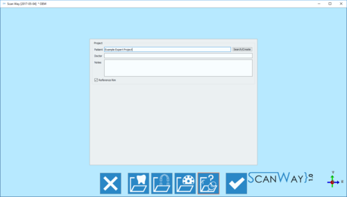
Example: Expert Project
このページでは、エキスパートモードでプロジェクトをスキャンする方法を説明します。この種類のプロジェクトにはウィザードがないので、プロジェクトの作成に必要な情報は、一般情報セクションのみです。
情報が何も提供されていないため、このプロジェクトでは固定のステップはなく、ユーザーはオブジェクトを任意の順番でスキャンできます。
今回のデモ用プロジェクトでは、上顎と、2つのダイのスキャン、アライメント、メッシュ生成を行います。
このデモで行われる操作の順番に従う必要はありませんが、アイテムのアライメントはメッシュ生成の前に実行することが推奨されます
Contents
上顎
スキャンを開始するには、スキャンボタン をクリックします。スキャンするオブジェクトについて何も指示がないため、ソフトウェアではスキャンプロファイル、また必要な場合は、アドバンス設定オプションを指定するよう求められます。アドバンス設定について詳しくは、スキャンインターフェース ページ -アドバンス設定のパラグラフを参照して下さい。
今回は以下のように定義します:
プロファイルを選択したら、上顎モデルのスキャンを開始できます。
モデルをモデルホルダーに置き、スキャンボタン をクリックします。スキャンが終了すると、結果が表示されます。
エキスパートプロジェクトではステップが段階に分かれています。次へ進むボタン をクリックすると編集モードに入ります。
利用可能なツールを使ってモデルを編集またはトリミングし、次へ進むボタンをクリックします。このステップで利用できるオプションについて詳しくは、編集ツールのページを参照して下さい。
Dies
In the Expert project it is not possible to use the multidie, since the software doesn't know which items will be scanned. Therefore the dies can be scanned in any possible way and combination. In our demo project we have two dies, and we'll proceed scanning them both on the model holder.
To start the scan, the profile needs to be selected:
At this point, the scan can be started. Place the dies on the chosen support and click the Scan Button . Once the scan is finished the result will be shown.
As for the previous item, by clicking the edit mode activates.
Two dies have been scanned together and are therefore saved in the same image. To be able to use them in a design project it is needed to separate the two items and create two different images.
To do so, right click on the Stump image in the items' list and click Clone Item Action.
Now edit and rename the two images, leaving only one element per image.
When all the items are in separate images, they can be aligned to their reference.
Alignment
Since this project doens't have a structure, the software cannot start the alignment automatically. The user needs to select the items to align and their reference.
All the items are now in position and the user can start editing the images for mesh generation.
Reference Editing
The reference editing is very important because it avoids exporting double surfaces to the CAD and consequential errors during design.
In Structured projects this step is completely automatic.
To delete double surfaces, click on the reference image (in this case the upper model) in the items' list and edit out the parts that were scanned separately.
Once all reference images have been edited the mesh can be generated.
Mesh Generation
As for the scans, different items get meshed in different ways. The user has to select a meshing profile for each item.
To then Export the generated meshes, right click on the meshed elements in the items' list and select Export Items. The software will ask the user to select the folder for the export.
