Alignment Interface
通常のアライメント
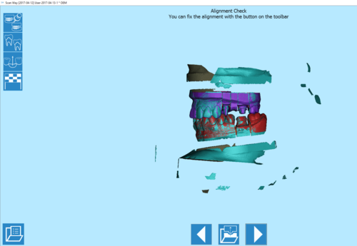
アライメントトは中間ステップですが、ほとんどの場合で自動で行われるため、ユーザーが意識することはあまりありません。実際、自動アラインメントが正しく行われた場合、ユーザーにはアライメント確認ウインドウのみ表示されます。
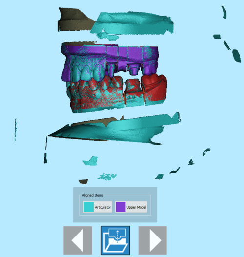
アライメント確認ウインドウには、特定のツールバーと、アライメントされたすべてのアイテムが異なる色で表示されます。
 戻る
戻る- 前のステップに戻ります。このアイコンは、最初のスキャンステップでは無効になっています。
 アライメント修正
- アライメントされたアイテムのリストが表示され、不適切なものがあれば修正できます
 次へ
次へ- プロジェクト内の次のステップに進みます。このオプションは、すべてのアイテムが識別されるまで利用できません。
![]() ボタンをクリックすると、アライメントされたアイテムのリストが表示されます。
ボタンをクリックすると、アライメントされたアイテムのリストが表示されます。
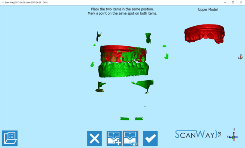
アライメントされたアイテムの1つをクリックすると、手動アライメントパネルが開きます。このパネルでは、自動的に実行されたアライメントをユーザーが修正できます。
表示されている手動アライメントステップのウインドウの中央に、固定されたまたはレファレンスの要素があり、これに詳細アイテムがアライメントされます。右上には、レファレンスと合致される移動可能なアイテムがあります。ツールバーもあります。
 終了
終了- オプションセクションを終了します。
 ベストフィット
- 2つの画像間のアライメントを修理します。このアクションは通常自動で実行されます。
 フローティング表示
- フローティング/移動アイテムの画像を表示または非表示にします。
 確定
確定- 変更内容を確定して、オプションセクションを閉じます。
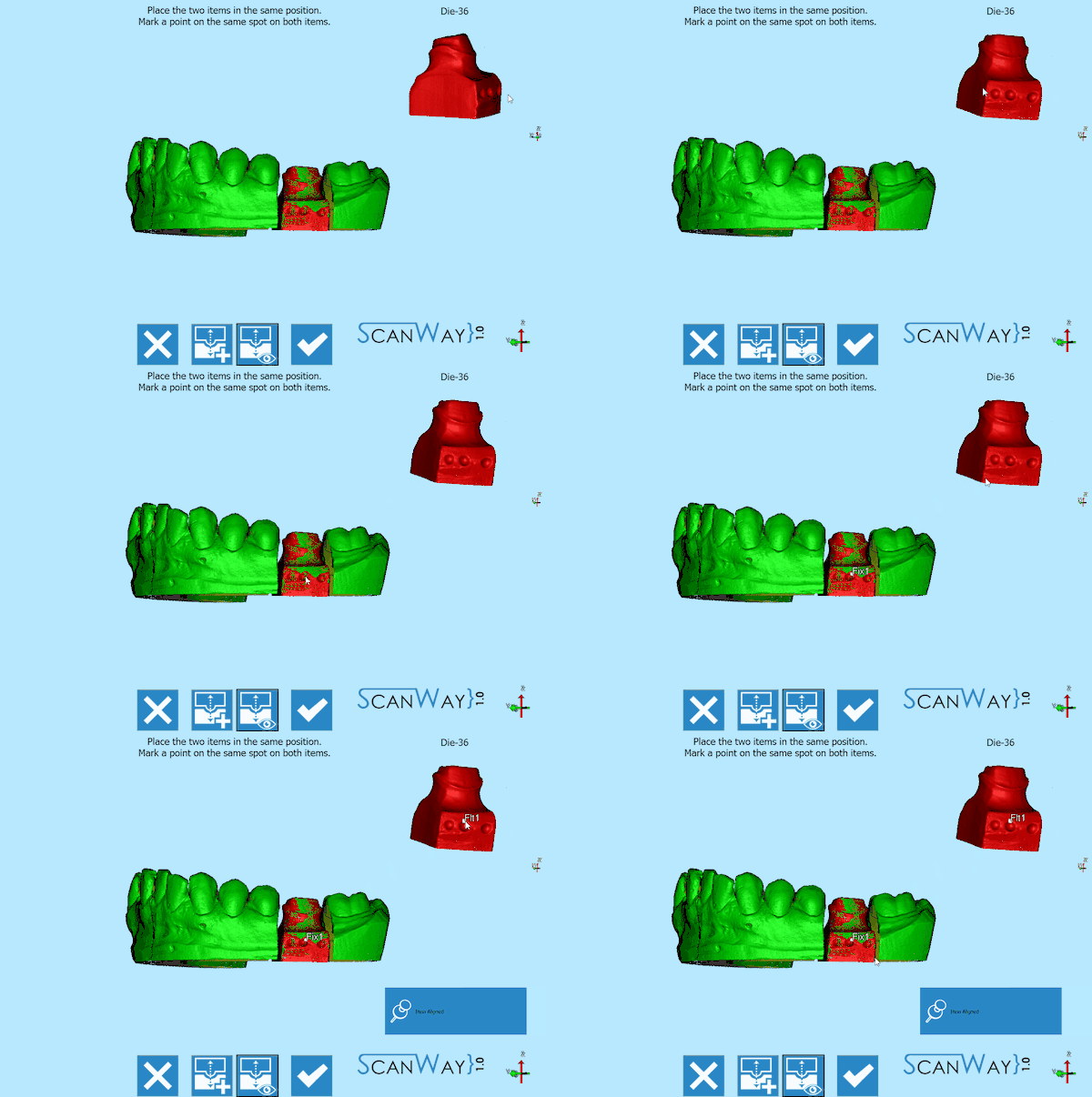
アライメントを実施するには、2つの画像(固定された画像と移動する画像)を同じ場所に置き、両方のアイテムの同じ場所にポイントをマークします。合わせるのが難しかったり、情報が不足している場合など、必要な場合は画像に複数のポイントをマークすることもできます。
変更内容を確定またはキャンセルして、プロジェクトを進めます。
インプラントマーカー
インプラントのプロジェクト用にデータを取得する際、インプラント自体を取得するのには問題があります。スタンプや石膏模型の一部を取得するのとは異なります。インプラントのコネクション/インターフェースは通常小さく、金属製です。
Moreover, the fitting has to be mechanically perfect, with no margin of error.
To solve this problem, the implant connection is not directly scanned but an Implant Marker or Scan Body is used instead. A Scan Body is a specific object, designed to be scanned, which fits exactly over the implant.
The scan of the implant marker itself is not enough: its resulting data will be used to compute the exact position of the implant interface. In order to carry out this operation, an Implant Library is needed .
The alignment to the implant library can be performed in the CAD software. However, using an implant library for Exocad's Platform, the user can perform this operation directly in the scanning software ScanWay, in order to get better results.
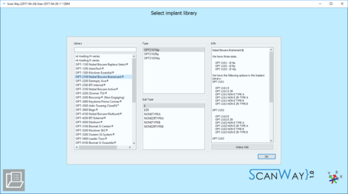
Library Selection
The implant library selection is automatically shown when all the items of the project have been acquired.
The Panel is divided in 4 Sections:
- Library
- For choosing the general connection and implant family, contains:
- A Filter box where it is possible to write part of the name of the needed implant. All the implants that match the name will be showed in the implant list
- An implant list with all the implants available in the current Implant Library
- Type and Sub Type
- For Choosing the diameter and type of connection. There can be many of these types, in our libraries for instance there are:
- Engaging Connections : the connection can not rotate on the implant, suggested for abutments or single restorations
- Not-Engaging Connections : the connection can rotate on the implant, suggested for bars and bridges
- For Zirconia : connections with specific shapes, suited for zirconia restorations
- Preview
- Shows the preview of the STL marker present in the library
- Info
- If the library is correctly configured to work with our software, in this section it is possible to have a small overview of the libraries with additional information on the availabe diameters and implant types.
All our libraries are provided with this feature and, being connected to this wiki, the Open in browser button opens the wiki on the implant list page.
To accept the implant selection click on Select, otherwise Cancel.
If the CAD design is launched using a wrong connection it will be necessary to restart all the design from the beginning
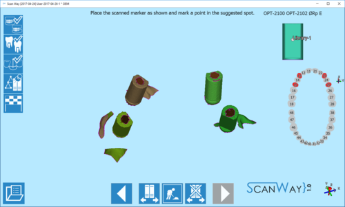
Marker Alignment
Once the library has been selected, the wizard shows the marker alignment step.
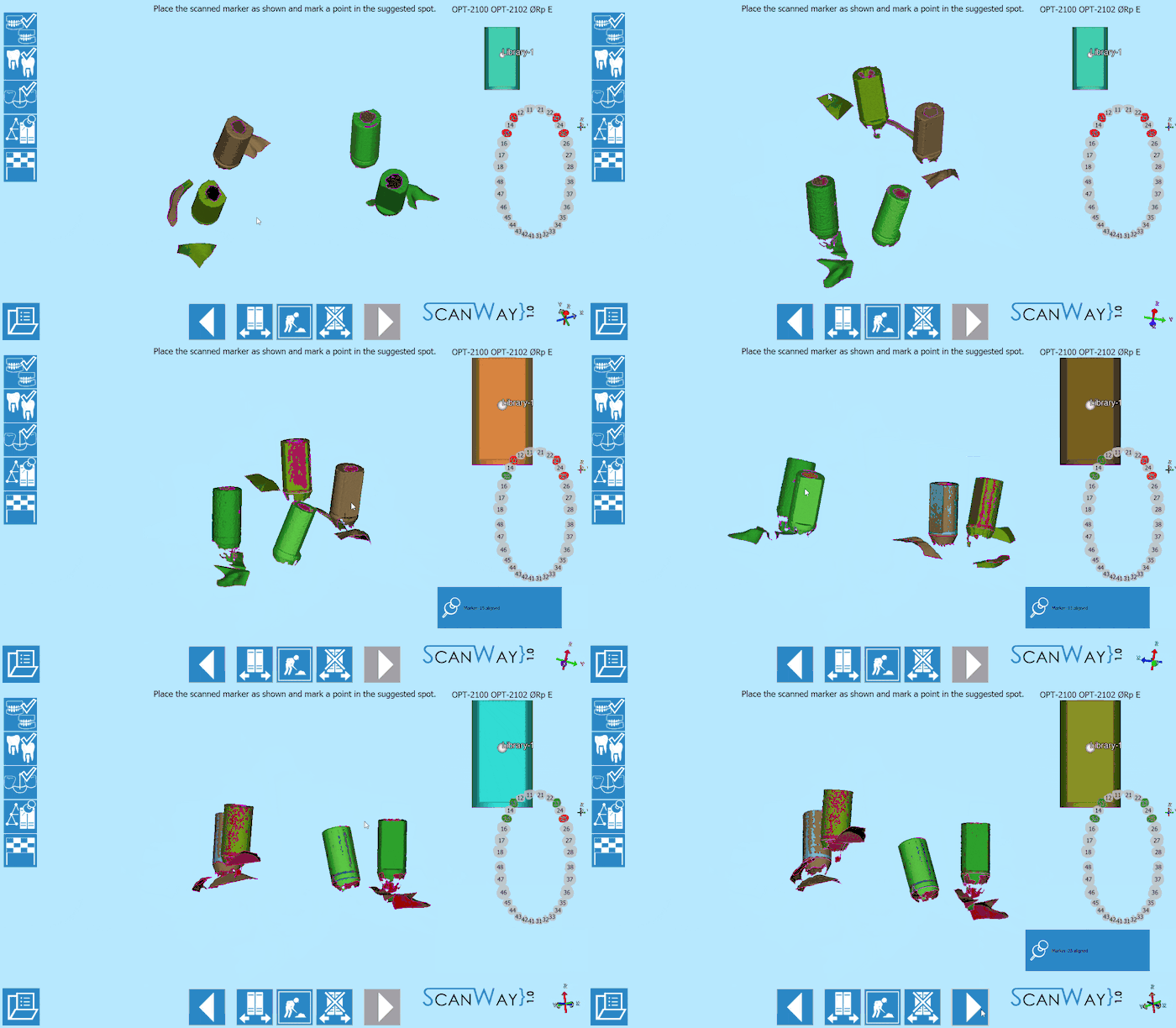
The interface shows all the acquired markers; an image of the STL of the library with a premarked point; a teeth graphic showing the elements that need to be aligned; a specific toolbar.
The toolbar offers this options:
 Previous
- Goes back to the previous step. Icon not active during the first scanning step.
 Change implant library
 - Allows to change implant library, for instance if in one case have been used different connections.
 Show model
 - Shows or hides the reference model underneath the markers.
 Reset
Reset- Restarts the alignment from the beginning.
 Next
Next- Goes forward one step in the project. This option is not available until all the items have been aligned.
To align it is simply necessary to move the scanned markers to mimic the position of the library STL shown in the upper right corner of the window. When the marker is in the correct position ,mark one point as suggested in the library image. Repeat for all the acquired elements, not necessarily following any order.
