Difference between revisions of "Scan/it"
(Created page with "Quando si lancia la scansione, verrà mostrato un cerchio di progressione del lavoro. L'acquisizione può essere fermata facendo click sul bottone {{Inline button|stopAction.p...") |
|||
| Line 19: | Line 19: | ||
;{{List button|nextAction.png}} Successivo: Prosegue di un passaggio nel progetto. Questa icona è disponibile quando il passaggio in corso è completo o i passaggi possono essere tralasciati. | ;{{List button|nextAction.png}} Successivo: Prosegue di un passaggio nel progetto. Questa icona è disponibile quando il passaggio in corso è completo o i passaggi possono essere tralasciati. | ||
| − | Quando si lancia la scansione, verrà | + | Quando si lancia la scansione, verrà segnalato su un cerchio lo stato di progressione del lavoro. L'acquisizione può essere fermata facendo click sul bottone {{Inline button|stopAction.png}}. |
===Integration=== | ===Integration=== | ||
Revision as of 12:22, 19 May 2017
Contents
Struttura
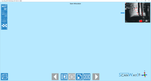
L'interfaccia di scansione è la parte della Modalità Guidata che regola l'acquisizione delle immagini 3D. La barra degli strumenti principale offre strumenti specifici per scansionare, mentre la vista live delle telecamere nell'angolo in alto a destra permette di controllare la posizione dell'oggetto nella camera di scansione e la quantità di luce che lo colpisce.
Barra degli Strumenti di Scansione
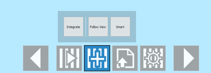
Le azioni nella barra degli strumenti di scansione possono variare a seconda del passaggio in corso. Di seguito una lista di tutte le possibili icone, delle loro applicazioni e del loro passaggio di riferimento:
 Precedente
- Torna al passaggio precedente. Icona non attiva durante il primo passaggio di scansione.
 Scansione
- Avvia la procedura di acquisizione specifica per il passaggio in corso. Questa icona è sempre disponibile.
 Integrare
- Permette di aggiungere immagini a quelle già acquisite per il passaggio in corso. Questa icona non è disponibile nel passaggio di scansione dell'articolatore e prima che la scansione sia concretamente effettuata. Questa azione verrà spiegata meglio più avanti in questa pagina.
 Importare
- Permette di importare un file per l'immagine richiesta invece di scansionare. Questa icona è sempre disponibile.
 Parametri Avanzati
- Permette di impostare una procedura di scansione differente per il passaggio in corso. Questa azione verrà spiegata meglio più avanti in questa pagina.
 Copiare da Riferimento
- Permette di copiare un'immagine precedentemente acquisita per il passaggio in corso. Questa azione è disponibile nei passaggi di scansione di Sani e intermedi, e di Cerature. Questa azione è completamente automatica, il che significa che l'immagine copiata è già mostrata nel passaggio senza dover fare click sull'icona corrispondente. L'utente può comunque decidere di scansionare nuovamente l'oggetto e poi copiare il primo riferimento se l'ultima scansione non lo soddisfa.
 Successivo
- Prosegue di un passaggio nel progetto. Questa icona è disponibile quando il passaggio in corso è completo o i passaggi possono essere tralasciati.
Quando si lancia la scansione, verrà segnalato su un cerchio lo stato di progressione del lavoro. L'acquisizione può essere fermata facendo click sul bottone ![]() .
.
Integration
The integration action allows to add information to the scan without having to rescan the object with the full procedure. By clicking on the Template:Inline Button button, the integration panel opens.
There are two way to carry out an integration. To choose one of the two methods click on the relevant button, to then start the integration click on the Integrate button:
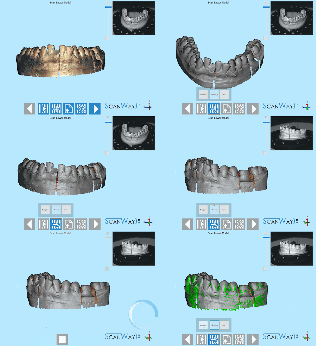
- Follow View
- Click on Follow View. Move the 3d object in the space and center the view on the missing information. Check that the point that you need to scan again is visible in the live view of the cameras and click on Integrate.
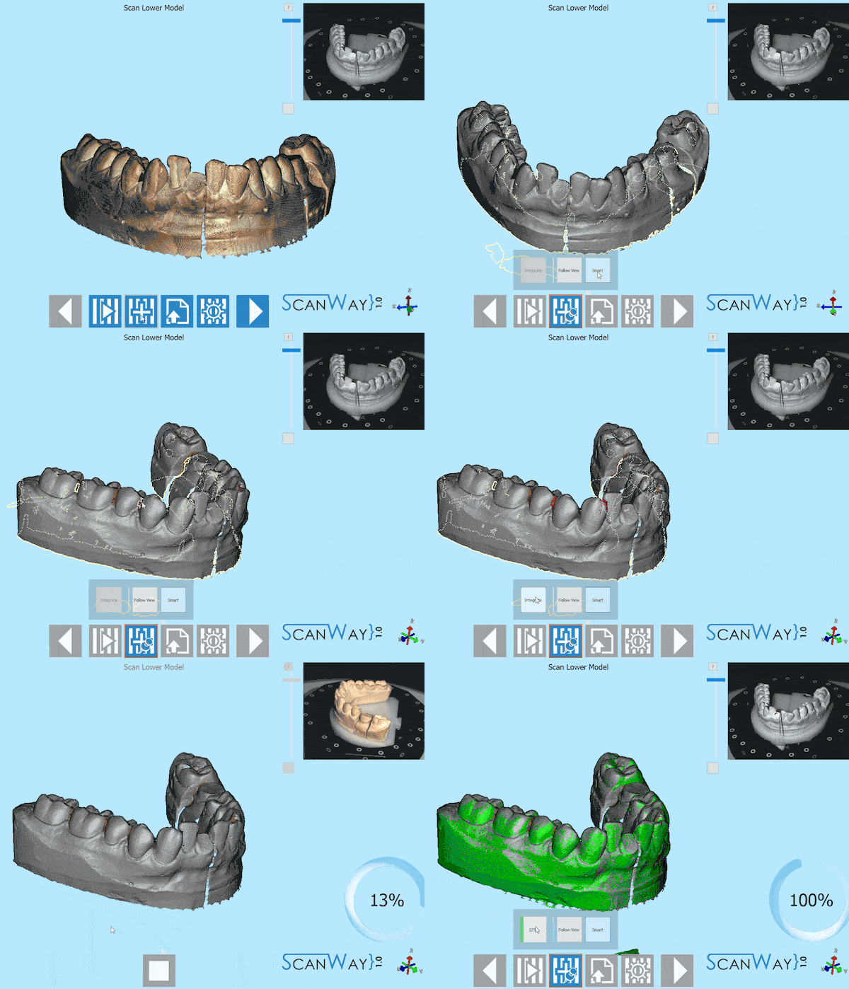
- Smart
- Click on Smart. A little progress bar will appear and, when it gets to 100%, all the holes or missing information will be marked in yellow on the acquired image. Left click near the yellow lines to select an area that needs to be rescanned. The selected areas will be marked in red. Click on integrate to launch the scan sequence that will try to cover up all the selected areas of missing information.
Advanced Parameters
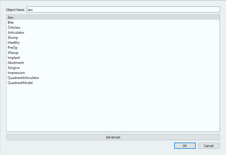
The Advanced Parameters button ![]() opens the profile and parameters selection dialog.
opens the profile and parameters selection dialog.
Every object is scanned with a different procedure, to get all the details of the different shapes that can be scanned and avoid to use an unnecessarirly elevated number of images for a reference object. For instance, the articulation scan will be performed with only four images on an horizontal plane and reduced speed to avoid loosing the balance of the occlusion; on the other hand, the models will be scanned with 6 images on a low tilt, the dies with 12 images on a higher tilt and so on.
These profiles are Open Technologies' suggestion on how to scan a determined object, but it is not said that they should be always the best procedures, seen that dental objects are seldom similar. Starting from this assumption, the user is always free to decide whether to change the scan profile or not by selecting any other voice in the profile list to increase or reduce the number of images and detail. Of course, the higher the level of detail, the hhigher the number of images, the heavier the resulting file.
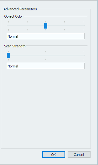
Moreover, by clicking Advanced on the bottom of the dialog, the user will be able to change some advanced parameters of the selected scanning profile.
There are two parameters atht can be modified:
- Object Color
- The shade of the specific kind of object. Like in the live view of the camaras, this parameters controls the amount of light that will hit the object; if the object is very dark it will need to be scanned with a brighter beam and vice versa.
- Scan Strenght
- This parameter allows to higher the contrast of the scanning pattern to better scan difficult surfaces (translucid, metallic etc). The more the selected strenght, the more time the scan will take.
Die Scan Definition
Die scanning works the same as all the other scanning steps, but it has an intermediate definition step with which the user can decide to either use the Multi die plate (default choice) or to mark a custom die scan setup.
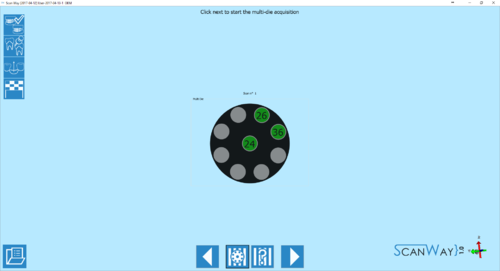
The multi die definiton ![]() appear automatically at the beginning of the dies scanning step. The 9 positions of the multi die will be filled starting from the elements of the first quadrant, if there are any, and follows the standard numbering order. The wizard will show in which position to insert each die. If the dies exceed the number of positions, a further step will be added to the wizard to scan all the elements defined in the project.
appear automatically at the beginning of the dies scanning step. The 9 positions of the multi die will be filled starting from the elements of the first quadrant, if there are any, and follows the standard numbering order. The wizard will show in which position to insert each die. If the dies exceed the number of positions, a further step will be added to the wizard to scan all the elements defined in the project.
If the multi die plate is used, the software will already know which die is in which position, and there will be no need to further identify the items that will be automatically aligned to their reference.
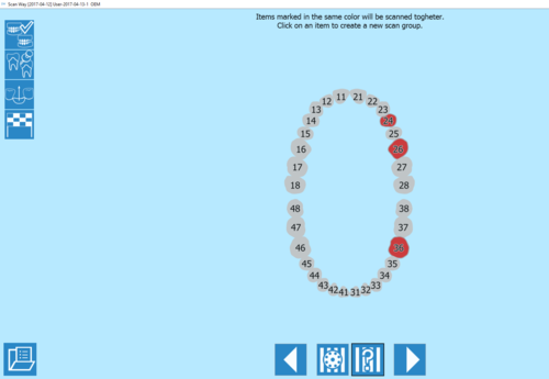
As an alternative to the use of the multi die plate, the user can set a custom die scan order by clicking on the custom setup ![]() button.
button.
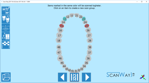
The software will mark all the items to be scanned in the same color which means that, by default, they would need to be scanned together. By clicking on one of the items to scan, the tooth will change color and will create a second scan group. Click then on all the items to be scanned in that second scan group. By clicking a second time on one of the already selected items, a further scan group will be created and marked in a third color. This operation can be repeated as many times as one wishes, remeber that all the items marked in the same color will be scanned together.
In this mode, the software cannot know which item is scanned in which position, therefore it will require the user to identify each stump. Identification procedure will be explained in the Edit Tools page.
Marker Scan Definition
The marker (or scanbodies) scan is similar to the custom setup of the dies scan.
The software will mark all the items to be scanned in the same color which means that, by default, they would need to be scanned together. By clicking on one of the items to scan, the tooth will change color and will create a second scan group. Click then on all the items to be scanned in that second scan group. By clicking a second time on one of the already selected items, a further scan group will be created and marked in a third color. This operation can be repeated as many times as one wishes, remeber that all the items marked in the same color will be scanned together.
The software cannot know which marker is scanned in which position, therefore it will require the user to identify each scanbody. Identification procedure will be explained in the Edit Tools page.
Live view
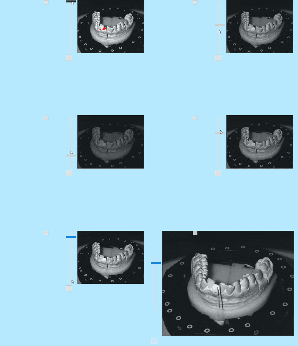
The live view of the software, on the upper right corner, allows to check the position of the object and the amount of light with which it will be scanned.
For different objects in the same project the light might need to be changed to avoid reflections and improve the scan quality.
The light intensity can be regulated using the bar on the left side of the window.
The red markings show the areas of the objects that are over-exposed and will be more problematic to acquire. Be careful not to lower too much the light intensity, as to do so, the scan quality will be worsened.
