Difference between revisions of "Scan/ja"
(Created page with "===統合===") |
(Created page with "統合アクションでは、オブジェクトを再スキャンせずに、スキャンに情報を追加できます。{{Inline button|integrateAction.png}} ボタンを...") |
||
| Line 23: | Line 23: | ||
===統合=== | ===統合=== | ||
| − | + | 統合アクションでは、オブジェクトを再スキャンせずに、スキャンに情報を追加できます。{{Inline button|integrateAction.png}} ボタンをクリックすると、'''統合パネル'''が開きます。 | |
[[File:Integrate-actions.png]] | [[File:Integrate-actions.png]] | ||
Revision as of 13:02, 18 September 2017
Contents
構造
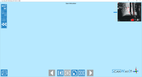
スキャンインターフェースは、ウィザードで3D画像の取得を制御する部分です。メインのツールバーにはスキャン用のツールがあり、右上にあるカメラのライブビューではスキャンチャンバー内のオブジェクトの位置やあてられている光量を確認できます。
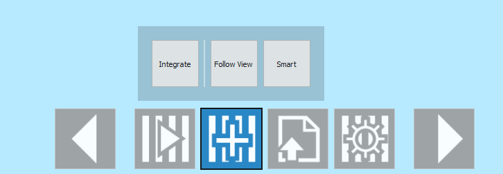
スキャンツールバー
スキャンツールバーでの操作は実行中の手順によって異なることがあります。表示されるすべてのアイコンのリスト、用途、および表示されるステップを以下に示します。
 戻る
戻る- 前のステップに戻ります。最初のスキャンステップでは、アイコンが無効になっています。
 スキャン
スキャン- 実行中のステップ固有の取得手順を開始します。このアイコンは常に利用可能です。
 統合
統合- 実行中のステップで取得済みのものに画像を追加できます。咬合器スキャンステップ中、またはスキャンを実際に実行する前は、このアイコンは利用できません。この操作については、このページの下部で詳しく説明します。
 インポート
インポート- スキャンする代わりに、必要な画像のファイルをインポートできます。このアイコンは常に利用可能です。
 詳細パラメーター
- 実行中のステップで異なるスキャン手順を設定できます。この操作については、このページの下部で詳しく説明します。
 レファレンスからコピー
- 実行中のステップで以前取得した画像をコピーできます。この操作は、健全歯およびポンティックで利用可能で、ワックスアップのスキャンステップでも利用できます。この操作は完全に自動化されているので、該当するアイコンをクリックしなくてもコピーされた画像はすでに表示されています。前回のスキャンの結果が思わしくない場合、ユーザーはオブジェクトを再スキャンしてから最初のレファレンスをコピーできます。
 次へ
次へ- プロジェクトの次のステップに進みます。実行中のステップが完了している、またはスキップできる場合、このアイコンは利用可能です。
スキャンを起動すると、進行状況を示すホイールが表示されます。スキャンを中止する場合は、![]() ボタンをクリックします。
ボタンをクリックします。
統合
統合アクションでは、オブジェクトを再スキャンせずに、スキャンに情報を追加できます。![]() ボタンをクリックすると、統合パネルが開きます。
ボタンをクリックすると、統合パネルが開きます。
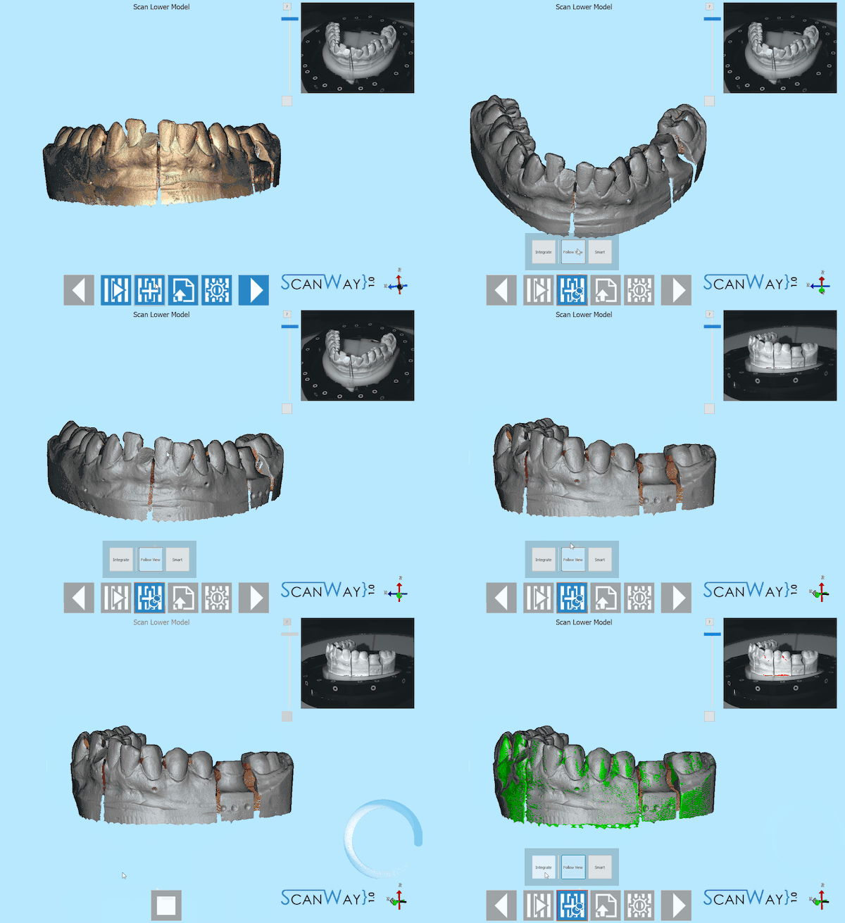
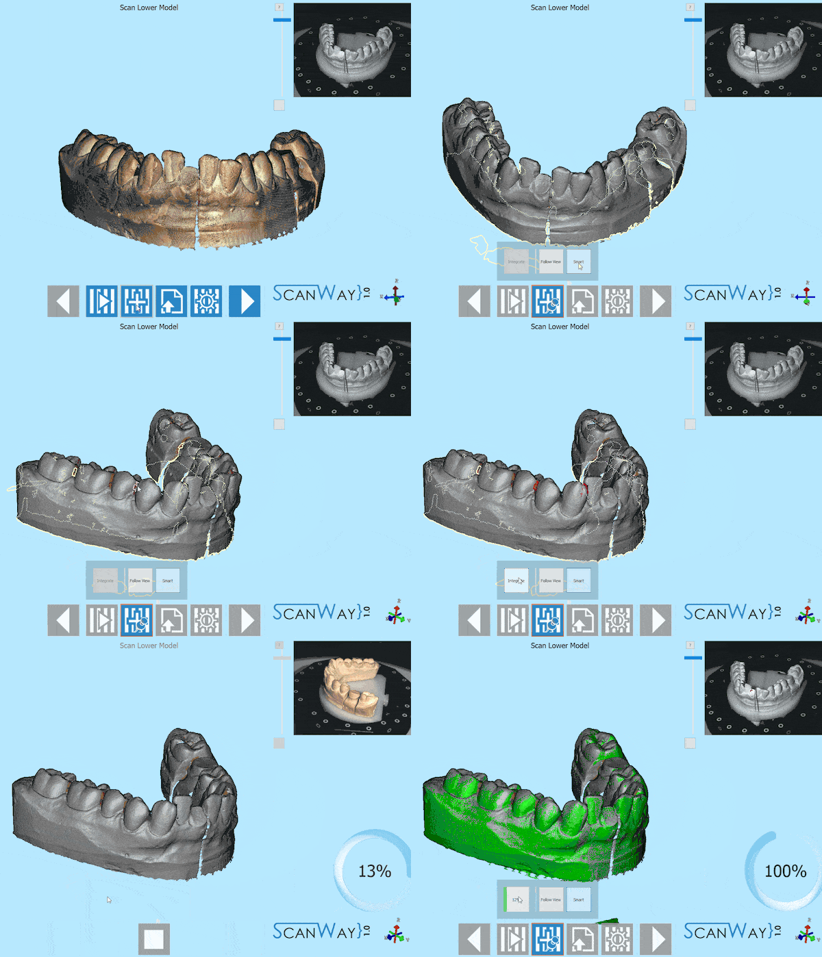
There are two way to carry out an integration. To choose one of the two methods click on the relevant button, to then start the integration click on the Integrate button:
- Follow View
- Click on Follow View. Move the 3D object in the space and center the view on the missing information. Check that the point that you need to scan again is visible in the live view of the cameras and click on Integrate.
- Smart
- Click on Smart. A little progress bar will appear and, when it gets to 100%, all the holes or missing information will be marked in yellow on the acquired image. Left click near the yellow lines to select an area that needs to be rescanned. The selected areas will be marked in red. Click on integrate to launch the scan sequence that will try to cover up all the selected areas of missing information.
Advanced Parameters
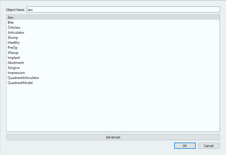
The Advanced Parameters button ![]() opens the profile and parameters selection dialog.
opens the profile and parameters selection dialog.
Every object is scanned with a different procedure, to get all the details of the different shapes that can be scanned and avoid to use an unnecessarily elevated number of images for a reference object. For instance, the articulation scan will be performed with only four images on an horizontal plan and reduced speed to avoid loosing the balance of the occlusion; on the other hand, the models will be scanned with 6 images on a low tilt, the dies with 12 images on a higher tilt and so on.
These profiles are Open Technologies' suggestion on how to scan a determined object, but it is not said that they should be always the best procedures, seen that dental objects are seldom similar. Starting from this assumption, the user is always free to decide whether to change the scan profile or not by selecting any other voice in the profile list to increase or reduce the number of images and detail. Of course, the higher the level of detail, the higher the number of images, the heavier the resulting file.
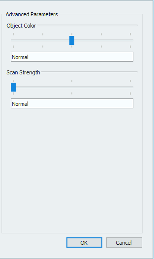
Moreover, by clicking Advanced on the bottom of the dialog, the user will be able to change some advanced parameters of the selected scanning profile.
There are two parameters that can be modified:
- Object Color
- The shade of the specific kind of object. Like in the live view of the cameras, this parameter controls the amount of light that will hit the object; if the object is very dark it will need to be scanned with a brighter beam and vice versa.
- Scan Strength
- This parameter allows to higher the contrast of the scanning pattern to better scan difficult surfaces (translucid, metallic etc). The more the selected strength, the more time the scan will take.
Die Scan Definition
Die scanning works the same as all the other scanning steps, but it has an intermediate definition step with which the user can decide to either use the Multi die plate (default choice) or to mark a custom die scan setup.
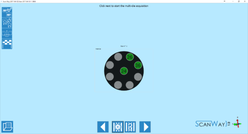
The multi die definiton ![]() appears automatically at the beginning of the dies scanning step. The 9 positions of the multi die will be filled starting from the elements of the first quadrant, if there are any, and follows the standard numbering order. The wizard will show in which position to insert each die. If the dies exceed the number of positions, a further step will be added to the wizard to scan all the elements defined in the project.
appears automatically at the beginning of the dies scanning step. The 9 positions of the multi die will be filled starting from the elements of the first quadrant, if there are any, and follows the standard numbering order. The wizard will show in which position to insert each die. If the dies exceed the number of positions, a further step will be added to the wizard to scan all the elements defined in the project.
If the multi die plate is used, the software will already know which die is in which position, and there will be no need to further identify the items that will be automatically aligned to their reference.
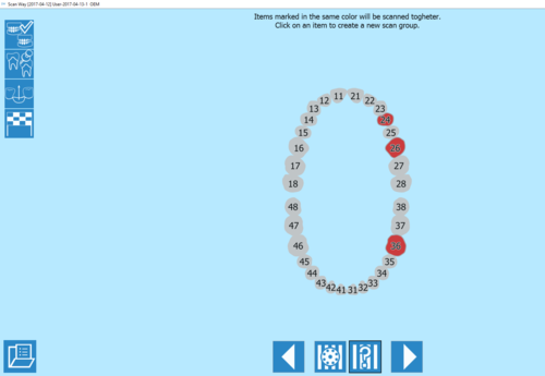
As an alternative to the use of the multi die plate, the user can set a custom die scan order by clicking on the custom setup ![]() button.
button.
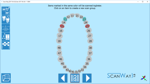
The software will mark all the items to be scanned in the same color which means that, by default, they would need to be scanned together. By clicking on one of the items to scan, the tooth will change color and will create a second scan group. Click then on all the items to be scanned in that second scan group. By clicking a second time on one of the already selected items, a further scan group will be created and marked in a third color. This operation can be repeated as many times as one wishes, remember that all the items marked in the same color will be scanned together.
In this mode, the software cannot know which item is scanned in which position, therefore it will require the user to identify each stump. Identification procedure will be explained in the Edit Tools page.
Marker Scan Definition
The marker (or scanbodies) scan is similar to the custom setup of the dies scan.
The software will mark all the items to be scanned in the same color which means that, by default, they would need to be scanned together. By clicking on one of the items to scan, the tooth will change color and will create a second scan group. Click then on all the items to be scanned in that second scan group. By clicking a second time on one of the already selected items, a further scan group will be created and marked in a third color. This operation can be repeated as many times as one wishes, remember that all the items marked in the same color will be scanned together.
The software cannot know which marker is scanned in which position, therefore it will require the user to identify each scanbody. Identification procedure will be explained in the Edit Tools page.
Live view
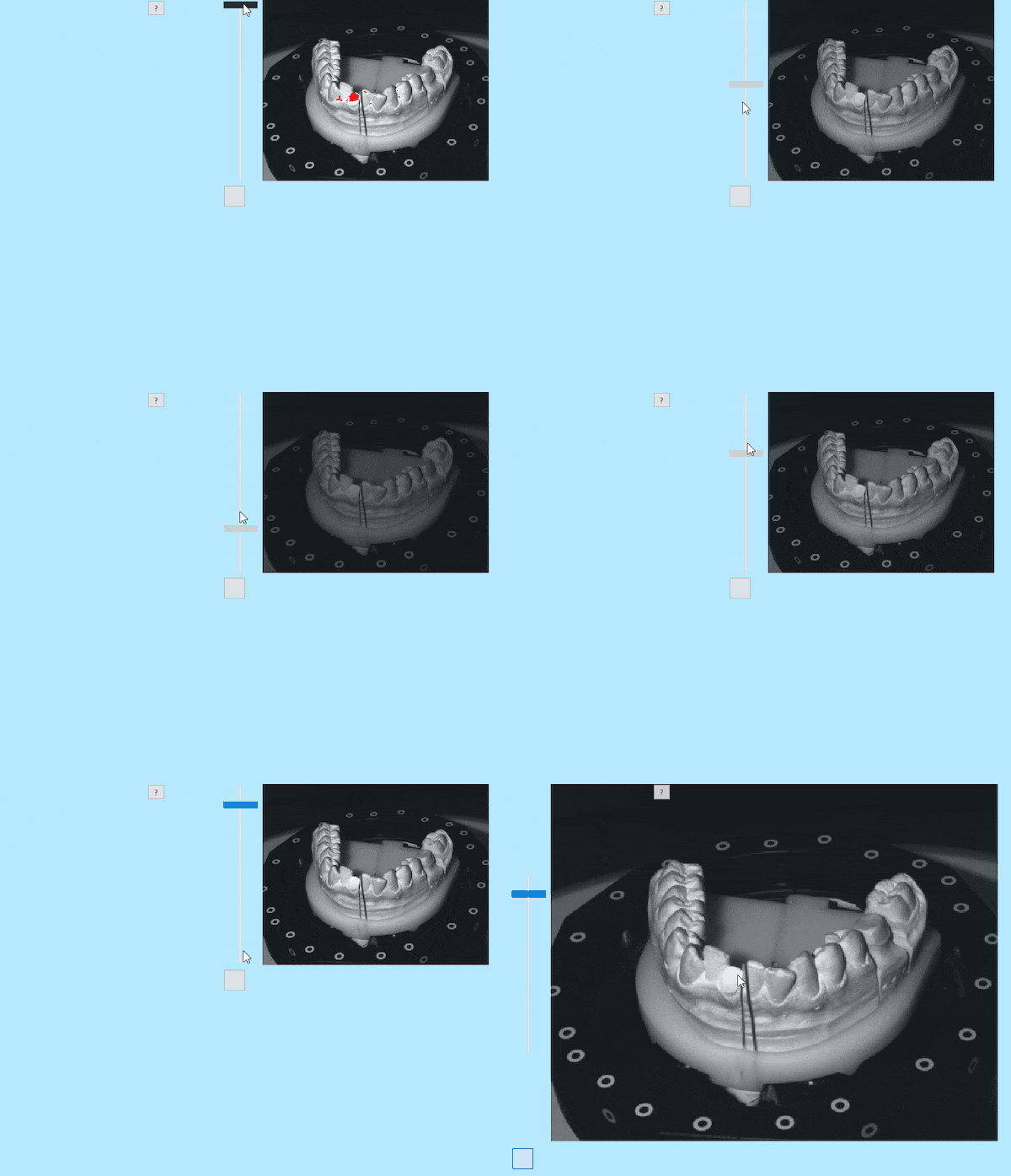
The live view of the software, on the upper right corner, allows to check the position of the object and the amount of light with which it will be scanned.
For different objects in the same project the light might need to be changed to avoid reflections and improve the scan quality.
The light intensity can be regulated using the bar on the left side of the window.
The red markings show the areas of the objects that are over-exposed and will be more problematic to acquire. Be careful not to lower too much the light intensity, as to do so, the scan quality will be worsened.
