Difference between revisions of "Calibrations"
(Marked this version for translation) |
|||
| Line 1: | Line 1: | ||
| − | {{DISPLAYTITLE:Calibrate | + | {{DISPLAYTITLE:Calibrate the scanner|noerror}} |
<translate> | <translate> | ||
Latest revision as of 15:02, 2 May 2018
To calibrate, access the service mode area from the welcome page, by clicking on Service.
The Service page allows the user to Check the scanner connection and to run all the calibrations the scanner needs to function correctly. To learn more about it go to the Service page.
In this page, it will be explained how to calibrate the scanner.
Recalibrate Head
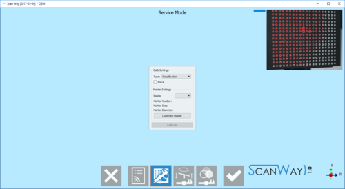
To launch this tool, click on the Head Calibration ![]() button;
button;
There are 2 types of calibration:
- Recalibration
- Fast procedure to update scanner's calibration periodically or to be performed if the scanner is moved to any other location
- Full Calibration
- More complex procedure to be performed after a mechanical repair
This tool uses the Calibration Kit to carry out a new calibration of the Optical Head of the scanner. The procedure is the following:
- Put the calibration kit inside the scanner in the correct position
- Select the calibration type from the drop-down menu
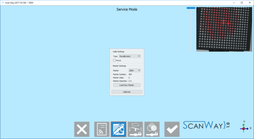
- In the calibration dialog, select from the drop-down menu the exact calibration kit name
- Click Start
If the calibration kit name is not available in the drop-down menu, the Load New Master XML button can be used to add a new calibration kit from the appropriate XML description file.
The calibration procedure is automatic. Once finished, the software will show one of the following messages:
- 'Scanner Already Calibrated' : the calibration is not necessary
- 'Scanner Recalibrated Successfully' : the calibration has been completed
- 'Scanner Recalibration Failed' : calibration has to be repeated
If the calibration was successful, the Axes Calibration starts automatically.
Recalibrate Axes
This tool is used to check the movement system of the scanner. The scanner will scan an object, analyze it, and use this data to calibrate the movement system.
This tool will start automatically after a Head Recalibration or can be started manually with the ![]() button.
button.
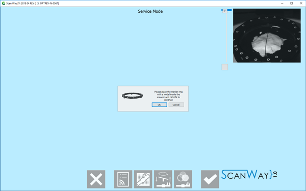
The software will prompt the user to insert the reference rim on the model holder
NOTE THAT THE REFERENCE RIM IS A PRECISION OBJECT! OCCLUSAL AND WHITENING SPRAYS, AND CLEANING SOLVENTS, DAMAGE ITS SURFACE!
DO NOT SPRAY ANY SUBSTANCE ON THE RIM AS TO DO SO IT WILL NO LONGER BE USABLE FOR SCANNING NOR FOR CALIBRATING!
When the Dynamic Articulation Module is enabled, calibrate the axis with the specific Axis Calibration Object. From that moment on, any recalibration needs to be performed with the same object. Otherwise, axis recalibration will fail.
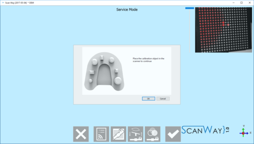
The software will show an image of the object needed to calibrate the scanner: either the calibration object (if the Dynamic articulation module is active on the license) or a stone model.
- Put the calibration object inside the scanner
- Click Recalibrate Axis
- Click Ok when prompted
The calibration procedure is automatic. Once it is finished, the software will show one of the following messages:
- 'Axes Recalibration Successfull' : the calibration has been completed,
- 'Axes Recalibration Successfull, Dynamic Articulation Calibration Failed' : the calibration has been completed, however, the dynamic articulation positioning will not work. This message shows when the dynamic articulation module is active on the license, but the scanner has been calibrated with a normal stone model.
- 'Axes Recalibration Failed' : calibration has to be repeated
Color Calibration
This last calibration, that can be opened by clicking on the icon ![]() , allows calibrating the acquired colors of the scanner to have realistic color results.
, allows calibrating the acquired colors of the scanner to have realistic color results.
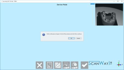
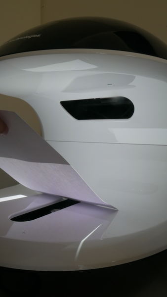
To calibrate the colors, hold a piece of paper in front of the cameras, as prompted by the message, and click OK.
It is important that the whole field is covered by the white paper. Take a look at the following pictures to replicate a correct positioning of the white sheet.
