Prosthesis Project
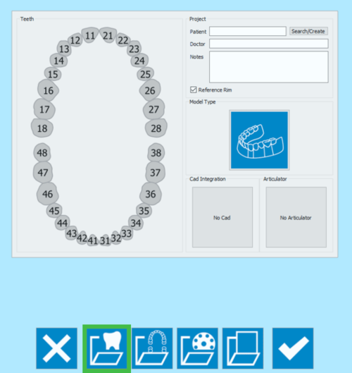
The first icon in the Project Creation page opens the Prosthesis Project definition.
The Project definition window is divided into 5 sections.
Tooth Definition
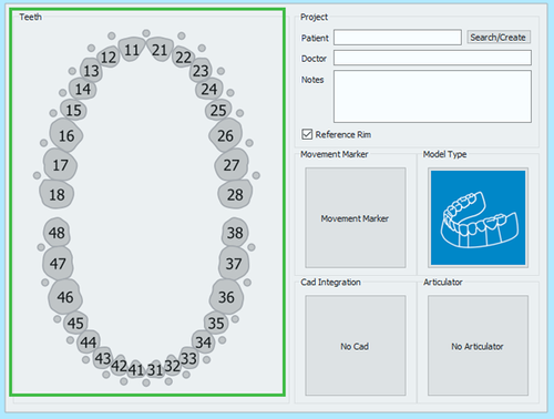
The first window on the left Teeth allows to select the items that will be scanned, their options and accesory scans.
By clicking on a element, the tooth definition panel opens.
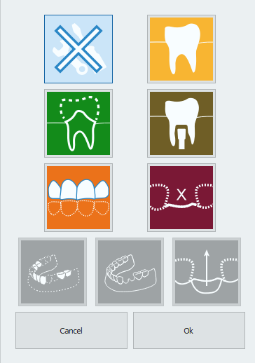
The possible choices are:
 None
None- Doesn't mark the tooth as part of the project and closes the tooth definition panel to go back to the previous step.
 Healty
- Marks the tooth as healty element. This tooth is part of the main stone model, it can be acquired with the rest of the model.
 Die
Die- Marks the tooth as a prepared die. This tooth is a removable die that has to be acquired alone or on the Multi-Die support
 Implant
- Signals that in the established position there is an implant, and a marker will be scanned.
 Antagonist
- Marks that the selected tooth is part of the opposing jaw.
 Pontic
- Marks the tooth as pontic element of a bridge.
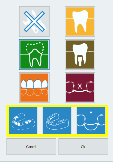
If an elements is marked as Die, Implant or Pontic, further options are made available:
 Waxup
Waxup- Indicates that on the selected tooth there is a Waxup element to be scanned.
 Situ
Situ- Indicates that for the selected tooth it there is a situ or pre operative model that has to be scanned.
 Gingiva
- Indicates that the selected element also has a gingiva item that will be scanned separatedly.
Once the tooth cathegory has been defined, and the options selected, accept with Ok or discanrd the changes with Cancel.
By holding ![]() when clicking on a tooth, the last defined element type will be copied to the selected tooth.
when clicking on a tooth, the last defined element type will be copied to the selected tooth.
By holding ![]() when clicking on a tooth, the last set parameters will be copied to all the teeth between the last tooth and the selected one.
when clicking on a tooth, the last set parameters will be copied to all the teeth between the last tooth and the selected one.
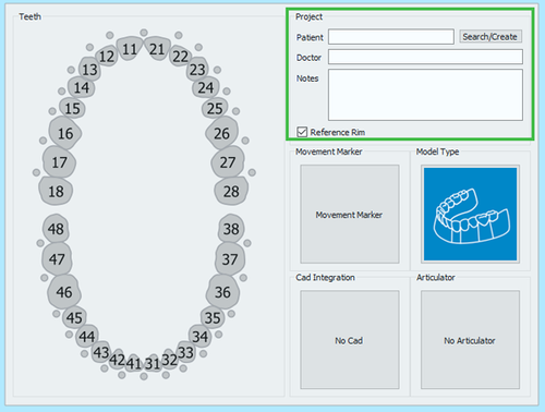
Project
The Project section allows the user to input some General Information:
- Patient's name
- Doctor's name (Optional)
- Notes (Optional)
- A check box to decide wether or not to use the Reference Rim.
It is possible to write freely in the Doctor and Notes boxes. As for the Patient, it is possible to:
- write freely in the box
- Create a new profile clicking on the Search/Create button
- Search the database for an already existing profile clicking on the Search/Create button
The Search/Create Button opens the following window:
This window allows to search the project database for already existing patients. A filter can be applied and, for those who use VDDS protocols, the research can be restricted to that specific database.
By clicking on the Create button, the following window opens:
The patient creation panel allows to input general information rrgarding the patient and the treatment, such as:
- The patient's name
- The patient's birth date
- The patient's Sex
- The doctor's name
- The patient's insurance ID, where applies
- Some notes
Once all the information has been filled in, select Ok to accept the data or Cancel to discard the changes and go back to the project definition page.
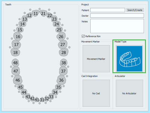
Model Types
This section allows to choose the kind of model that will be scanned.
By clicking on the model image, a model selection panel opens.
The available choices are:
 Unsectioned Model
 - enable this option if the model to be scanned is not sectioned, the scanner will not require a separate scan for every die
 Sectioned Model
 - default workflow, in which every element is acquired separately and all the information gets merged at the end
 Quadrant Model
 - if the Concept Quad Scan Module is enabled, it is possible to scan all the parts of a Quadrant Tray in just one step
 Impression Scan
 - if the Impression Scan Module is enabled in the license, check this option to scan an impression and not a stone model
Cad Integration
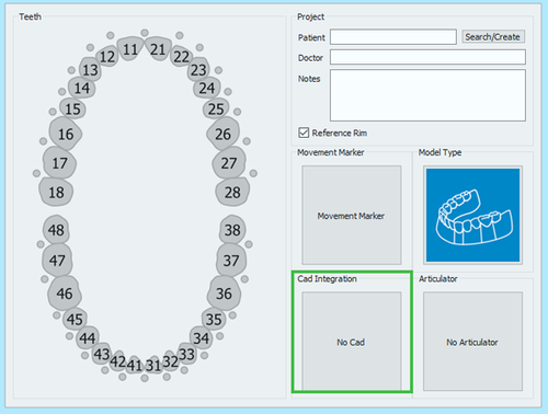
When the project is started directly from Exocad, the STL files produced in the scanning process will be transmitted to Exocad in just one click. On the other end, if the project gets created in the scanning software, the automatic export to CAD will not be configured, unless it is selected in this section.
By by clicking on the No Cad box the CAD selection window opens.
and it allows to choose one of the software integrated with our scanning system for automatic trasmission of the STL information.
- Exocad
- VDDS protocol (for orthodontics)
- Onyx Ceph (for orthodontics)
If No Cad is selected, the software will then ask the user to define an export path for the STL files.
Articulators
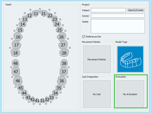
The last section allows to select an articolator to use the Dynamic Articulation Module.
If the Dynamic Articulation module is not active on the license this section will not be available
File:Articulator selection.png
Remember that it is always possible to scan any kind of articulator, this section is only to be used if you want to scan with the dynamic articulation module and pass the occlusion position in the Virtual Articulator of Exocad.
The Articulators available in Exocad and therefore in our software are:
 Artex
Artex - to scan the Artex Articulator and to use the same in Exocad's Virtual Articulator
 Sam/ Adesso
 - to scan the Sam Articulator or the Adesso splitcast and to use the same in Exocad's Virtual Articulator
 Protar- Kavo
 - to scan the Kavo Articulator and to use the same in Exocad's Virtual Articulator
 A7 - Bioart
 - to scan the Bioart Articulator and to use the same in Exocad's Virtual Articulator
 Denar by Whipmix
 - to scan the Denar Articulator and to use the same in Exocad's Virtual Articulator
