Difference between revisions of "ExamplesCemented/ja"
(Created page with "今回のデモ用プロジェクトでは以下の通りプロジェクトを定義します。") |
(Updating to match new version of source page) |
||
| (97 intermediate revisions by one other user not shown) | |||
| Line 3: | Line 3: | ||
このページでは、咬合する2つのモデルと3つのダイ(上顎に2つ、下顎に1つ)をスキャンする例を、ウィザードに従って説明します。 | このページでは、咬合する2つのモデルと3つのダイ(上顎に2つ、下顎に1つ)をスキャンする例を、ウィザードに従って説明します。 | ||
| − | == | + | <div class="mw-translate-fuzzy"> |
| + | ==Exocadでプロジェクト定義を開始する== | ||
このプロジェクトをExocadで作成するには、デスクトップでDentalDBアイコンをクリックします。プロジェクトマネージャーが開きます。 | このプロジェクトをExocadで作成するには、デスクトップでDentalDBアイコンをクリックします。プロジェクトマネージャーが開きます。 | ||
| + | </div> | ||
プロジェクト情報、設計する修復の種類、その他のパラメーターを入力します。この種類のプロジェクトでは、'''Scan Mode'''(スキャンモード)が'''Two stone models in occlusion'''(咬合する2つの石膏模型)に設定されていることを確認して下さい。 | プロジェクト情報、設計する修復の種類、その他のパラメーターを入力します。この種類のプロジェクトでは、'''Scan Mode'''(スキャンモード)が'''Two stone models in occlusion'''(咬合する2つの石膏模型)に設定されていることを確認して下さい。 | ||
| Line 15: | Line 17: | ||
[[File:prj_definition_exo.gif]] | [[File:prj_definition_exo.gif]] | ||
| − | + | プロジェクトの定義が完了したら、Actions(アクション)セクションの'''OPT'''をクリックして、スキャンソフトウェアを起動します。 | |
[[File:exo_to_scanway.gif]] | [[File:exo_to_scanway.gif]] | ||
| − | + | スキャンソフトウェアでは、Exocadで作成されたプロジェクトが最初に表示されます。プロジェクトが正しく定義されている場合は、確定ボタン {{Inline button|ok.png}} をクリックします。 | |
| − | == | + | ==ScanWayでプロジェクト定義を開始する== |
| − | + | すべてのプロジェクトは、後で設計に使用するCADにかかわらず、スキャンソフトウェアでも定義できます。 | |
| − | + | デスクトップのScanWayアイコンをダブルクリックして、スキャンソフトウェアを起動します。[[Splash|ようこそページ]]が開きます。プロジェクトを作成するには、最初のアイコンをクリックします。 | |
{{Screenshot|NewPrjIcon.png}} | {{Screenshot|NewPrjIcon.png}} | ||
| − | + | プロジェクトの定義方法について詳しくは、[[NewPrj|新規プロジェクトの作成]]のページを参照して下さい。 | |
| − | + | 今回のデモ用プロジェクトでは以下の通り定義します。 | |
[[File:prj_definition_cemented.gif]] | [[File:prj_definition_cemented.gif]] | ||
| − | + | どちらの方法でプロジェクトを定義しても、同じウィザードに進みます。ここからは、このウィザードに従っていきます。 | |
| − | == | + | ==ステップ1: 咬合器スキャン== |
| − | + | 両顎を持つように設定されたすべてのプロジェクトの最初のステップは、咬合器スキャンです。 | |
| − | ''' | + | '''咬合器スキャンと言っても、必ず咬合器をスキャンする必要はありません。このスキャンでは、専用サポート上で咬合器をスキャンするか、またはモデルホルダーで2つのモデルを咬合させてスキャンします。''' |
| − | + | <div class="mw-translate-fuzzy"> | |
| + | ユーザーが咬合器をスキャンする必要がある場合は、後ろへ傾けることをおすすめします。こうすることで、できるだけ多くの情報を得ることができるようになります。傾けることができない咬合器もあるので、その場合は不要です。 | ||
| + | </div> | ||
[[File:articulator_positions.png]] | [[File:articulator_positions.png]] | ||
| − | + | <div class="mw-translate-fuzzy"> | |
| + | スキャンインターフェースのライブビューでは、咬合器がまっすぐ置かれていると、咬合状態を正確に取得するのが難しくなることが実際に確認できます。 | ||
| + | </div> | ||
[[File:live_arti_posizioni.png]] | [[File:live_arti_posizioni.png]] | ||
| − | + | 一方、前述のように、咬合させた2つのモデルを輪ゴムやワックスで固定して、通常のモデルホルダー上でスキャンすることも可能です。 | |
[[File: arti-modelli.png]] | [[File: arti-modelli.png]] | ||
| − | + | オブジェクトをスキャナーに置いたら(咬合器を使って、またはモデルを重ねて)、'''スキャンボタン'''{{Inline button|scanAction.png}} でスキャンを開始できます。スキャンが終了すると、結果が表示されます。 | |
[[File: articulator-steps.png]] | [[File: articulator-steps.png]] | ||
| − | + | 利用可能なその他の機能については、[[Scan|スキャンインターフェース]]のページを参照して下さい。 | |
| − | + | {{Inline button|nextAction.png}} をクリックして、ウィザードの次のステップに進みます。 | |
| − | == | + | ==ステップ2: 下顎== |
| − | + | 両顎を持つように設定されたすべてのプロジェクトでは、2番目のステップとして下顎モデルをスキャンします。咬合器を除くすべてのステップには、2つのサブステップ(実際のスキャンと、取得された画像の編集)があります。 | |
| − | === | + | ===スキャンステップ=== |
| − | + | 下顎モデルをモデルホルダーに置き、'''スキャンボタン'''{{Inline button|scanAction.png}} をクリックします。スキャンが完了すると、結果が表示されます。 | |
[[File:lower-model-steps.png]] | [[File:lower-model-steps.png]] | ||
| − | + | <div class="mw-translate-fuzzy"> | |
| + | このスキャンはリファレンスリムを使って実行します。ユーザーがモデル、ダイ、またはマーカーのスキャンを起動する際、ソフトウェアでリファレンスリムが使用されていないことが検出されると、以下のメッセージが表示されます。 | ||
| + | </div> | ||
{{Screenshot|msg_rr.png}} | {{Screenshot|msg_rr.png}} | ||
| − | + | <div class="mw-translate-fuzzy"> | |
| + | ユーザーは、スキャンをキャンセルしてモデルホルダーにリファレンスリムを設置し、新しいスキャンを開始するか、リファレンスリムなしでスキャンを続行するかを決めることができます。リファレンスリムについて詳しくは、[[Accessories|付属品]]のページを参照して下さい。 | ||
| + | </div> | ||
| − | + | {{Inline button|nextAction.png}} をクリックして、下顎モデルステップの次の手順に進みます。 | |
| − | === | + | ===編集ステップ=== |
| − | + | <div class="mw-translate-fuzzy"> | |
| + | このステップでは、取得した画像を編集できます。このステップで利用できるオプションについて詳しくは、[[Edit|編集ツール]]のページを参照して下さい。 | ||
| + | </div> | ||
| − | + | <div class="mw-translate-fuzzy"> | |
| + | この段階の画像は編集したりトリミングしたりできます。ただし、この段階では画像に対してあまり大きな編集を行ったり、多くの情報を切り取ったりしないことが重要です。このような編集により、オブジェクトとリファレンスモデルとの自動アライメントの計算が困難になる場合があります。 | ||
| + | </div> | ||
| − | + | 画像の編集は、選択ツールを使って実行できます。 | |
[[File:edit_seltools.gif]] | [[File:edit_seltools.gif]] | ||
| − | + | 一方、トリミングは'''ベースカット'''ツールを使用すると非常に簡単に行えます。 | |
[[File:cut-base.gif]] | [[File:cut-base.gif]] | ||
| − | + | 適切な結果が取得できたら、{{Inline button|nextAction.png}} をクリックして次のステップに進みます。 | |
| − | === | + | ===ステップ3: 上顎モデル=== |
| − | + | 上顎モデルのスキャンでは、下顎モデルと同じように、2つのステップを実行する必要があります。 | |
| − | === | + | ===スキャンステップ=== |
| − | + | 上顎モデルをモデルホルダーに置き、'''スキャンボタン'''{{Inline button|scanAction.png}} をクリックします。スキャンが完了すると、結果が表示されます。 | |
[[File:upper-model-steps.png]] | [[File:upper-model-steps.png]] | ||
| − | + | リファレンスリムがモデルホルダーに置かれていない場合は、ここでも前述のメッセージが表示されます。 | |
| − | + | {{Inline button|nextAction.png}} をクリックして、上顎モデルの編集ステップに進みます。 | |
| − | === | + | ===編集ステップ=== |
| − | + | 上顎モデルもまだ編集可能です。ここでは、別の選択ツールを使って画像を編集します。 | |
[[File:edit-upper.gif]] | [[File:edit-upper.gif]] | ||
| − | + | 適切な結果が取得できたら、{{Inline button|nextAction.png}} をクリックして次の手順に進みます。 | |
| − | == | + | ==保存とアライメント== |
| − | + | {{Inline button|nextAction.png}} ボタンを押すと、ソフトウェアではすぐに保存が実行され、スキャンされたアイテムがそれぞれのリファレンスに対して自動でアライメントされます。 | |
[[File:save_and_align.gif]] | [[File:save_and_align.gif]] | ||
| − | + | <div class="mw-translate-fuzzy"> | |
| + | 自動アライメントおよび手動による手順については、[[Align|アライメントインターフェース]]のページを参照して下さい。 | ||
| + | </div> | ||
| − | == | + | ==ステップ4: ダイのスキャン== |
| − | + | <div class="mw-translate-fuzzy"> | |
| + | ダイのスキャンに必要なステップは、ユーザーが選択したスキャン方法(マルチダイプレートを使用するか、カスタム設定を使用するか)によって異なります。 | ||
| + | </div> | ||
| − | === | + | ===マルチダイ使用時=== |
| − | + | <div class="mw-translate-fuzzy"> | |
| + | デフォルトではこの方法が適用されています。この場合、マルチダイプレート上でソフトウェアが指示する位置にユーザーがダイを置いていきます。これにより各ダイが直ちに識別されます。 | ||
| + | </div> | ||
| − | ; | + | <div class="mw-translate-fuzzy"> |
| + | ;定義: 前述の通り、マルチダイプレートのダイの位置はソフトウェアによって事前に認識されています。 | ||
| + | </div> | ||
| − | + | <div class="mw-translate-fuzzy"> | |
| + | マルチダイの順番はユニバーサル方式に基づいており、最初の片顎の最後の部品から開始して、時計回りの順番になっています。これにより、中央に配置するダイは、常に最初の片顎の最後の部品に最も近いものとなります。<br /> ダイが9個を超える場合、追加の定義ステップが表示されます。 | ||
| + | </div> | ||
{{Screenshot|wizard-multidie-def.png}} | {{Screenshot|wizard-multidie-def.png}} | ||
| − | + | {{Inline button|nextAction.png}} をクリックして、マルチダイスキャンステップに進みます。 | |
| − | ; | + | <div class="mw-translate-fuzzy"> |
| + | ;スキャン: マルチダイスキャンインターフェースはすでに紹介したほかのステップに似ていますが、相違点として、マルチダイのリファレンスがウインドウ右側のライブビューの下にリマインダーとして表示されます。<br /> 続行するには、'''スキャンボタン'''{{Inline button|scanAction.png}} をクリックします。スキャンが終了すると、結果が表示されます。 | ||
| + | </div> | ||
[[File:multidie-steps.png]] | [[File:multidie-steps.png]] | ||
| − | + | {{Inline button|nextAction.png}} をクリックして、マルチダイスキャンの編集ステップに進みます。 | |
| − | ; | + | ;編集: 編集ステップでは、以前のステップで表示されたものと同じツールが利用できます。今回のケースでは、2つ以上のツールを適用する必要があります。 |
[[File:edit-multidie.gif]] | [[File:edit-multidie.gif]] | ||
| − | + | 適切な結果が取得できたら、{{Inline button|nextAction.png}} をクリックして次のステップに進みます。 | |
| − | ; | + | <div class="mw-translate-fuzzy"> |
| + | ;アライメント: 編集が終わったら、ダイがリファレンスに対してアライメントされ、結果がモニター上に表示されます。アライメントを変更したり、修正したり、やり直したりする場合は、[[Align|アライメントインターフェース]]のページを参照して下さい。 | ||
| + | </div> | ||
[[File:dies-autoalign.gif]] | [[File:dies-autoalign.gif]] | ||
| − | === | + | ===カスタム設定(マルチダイなし)=== |
| − | + | <div class="mw-translate-fuzzy"> | |
| + | モデルベース上のダイをスキャンする必要がある場合など、カスタムの順番でダイをスキャンすることもできます。カスタム設定による定義を行うには、ソフトウェアでマルチダイの定義が表示されたときに {{Inline button|customSetupAction.png}} アイコンをクリックします。 | ||
| + | </div> | ||
{{Screenshot|custom-setup-dies.png}} | {{Screenshot|custom-setup-dies.png}} | ||
| − | ; | + | <div class="mw-translate-fuzzy"> |
| + | ;定義: このソフトウェアでは、デフォルトで一意となるスキャングループが表示されます。これは、ほかで定義されていない限り、すべての支台歯を同時にスキャンするよう求められることを意味します。今回のケースでは、2つ目のスキャングループが作成されていて、上顎のダイと下顎のダイのスキャンを分割しています。{{Inline button|nextAction.png}} をクリックして、スキャンステップに進みます。 | ||
| + | </div> | ||
{{Screenshot|def_stumps.png}} | {{Screenshot|def_stumps.png}} | ||
| − | ; | + | ;スキャン: 作成したスキャングループの数によって、1つまたは複数のスキャンステップが設定されます。 |
| − | + | まずは、ダイをスキャナーに入れて、最初のグループのアイテムを取得する必要があります。<br /> リマインダーとして、同時にスキャンされるアイテムがウインドウ右側のライブビューの下にマークされて表示されます。 | |
| − | + | 次に、2つ目のグループに選択されたアイテムを入れるよう求められます。2つ目のスキャンは個別のダイなので、右側にリマインダーは表示されません。{{Inline button|nextAction.png}} をクリックして続行します。 | |
[[File:dies-steps.png]] | [[File:dies-steps.png]] | ||
| − | ; | + | <div class="mw-translate-fuzzy"> |
| + | ;ダイの識別: スキャングループに複数のアイテムがある場合、ユーザーは各ダイをそれぞれ正しく識別するよう求められます。<br /> このステップはスキャンステップの間で発生します。ダイの識別について詳しくは、[[Scan|スキャンインターフェース]]のページを参照して下さい。 {{Inline button|nextAction.png}} をクリックして続行します。 | ||
| + | </div> | ||
[[File:extract _24_26.gif]] | [[File:extract _24_26.gif]] | ||
| − | ; | + | ;編集: スキャングループに単一のダイしかない場合、識別するステップは発生せず、編集ステップが表示されます。{{Inline button|nextAction.png}} をクリックして続行します。 |
| − | ; | + | <div class="mw-translate-fuzzy"> |
| + | ;アライメント: 編集または識別されると、ダイはリファレンスに対してアライメントされ、結果がモニター上に表示されます。アライメントを変更したり、修正したり、やり直したりする場合は、[[Align|アライメントインターフェース]]のページを参照して下さい。 | ||
| + | </div> | ||
| − | == | + | ==ステップ5: 健全部分とポンティック== |
| − | + | <div class="mw-translate-fuzzy"> | |
| + | この段階でプロジェクトのスキャンは終わっていますが、ユーザーが健全部分やポンティックを再スキャンしたい場合もあります。実際、このステップは、スキャンされたリファレンスモデルのスキャンから、個別にスキャンした部分(今回の場合はダイ)をトリミングしたものです。 最初のモデルスキャンで、健全部分の接触点が正しく認識されないことがあり、その場合ユーザーはモデルを再スキャンする必要があります。そうでない場合は、{{Inline button|nextAction.png}} をクリックして続行します。 | ||
| + | </div> | ||
[[File:Healty-both.png]] | [[File:Healty-both.png]] | ||
| − | + | その後、ソフトウェアには詳しい編集ステップが表示されるので、ユーザーは健全部分の画像を編集できます。編集ステップでは、前述の説明に従って下さい。 | |
| − | == | + | ==ステップ6: メッシュ生成およびエクスポート== |
| − | + | <div class="mw-translate-fuzzy"> | |
| + | この時点で、ソフトウェアは自動的にメッシュ生成を開始します。メッシュは編集したり、個別にエクスポートしたり、画像としてエクスポートしたりできます。メッシュの編集について詳しくは、[[Mesh|メッシュツール]]のページを参照して下さい。 | ||
| + | </div> | ||
| − | + | エクスポートボタン {{Inline button|exportToCadAction.png}} をクリックして、CADにエクスポートします。 | |
{{Screenshot|Wizard-interface.PNG}} | {{Screenshot|Wizard-interface.PNG}} | ||
| − | + | <div class="mw-translate-fuzzy"> | |
| + | プロジェクトをExocadから開始した場合、CADが自動的に開き、すぐに設計を始めることができます。それ以外の場合は、ファイルをエクスポートする方法を選択するよう求められます。 | ||
| + | </div> | ||
{{Navigation|Examples|ExamplesImplants}} | {{Navigation|Examples|ExamplesImplants}} | ||
Latest revision as of 15:30, 1 June 2018
このページでは、咬合する2つのモデルと3つのダイ(上顎に2つ、下顎に1つ)をスキャンする例を、ウィザードに従って説明します。
Contents
Exocadでプロジェクト定義を開始する
このプロジェクトをExocadで作成するには、デスクトップでDentalDBアイコンをクリックします。プロジェクトマネージャーが開きます。
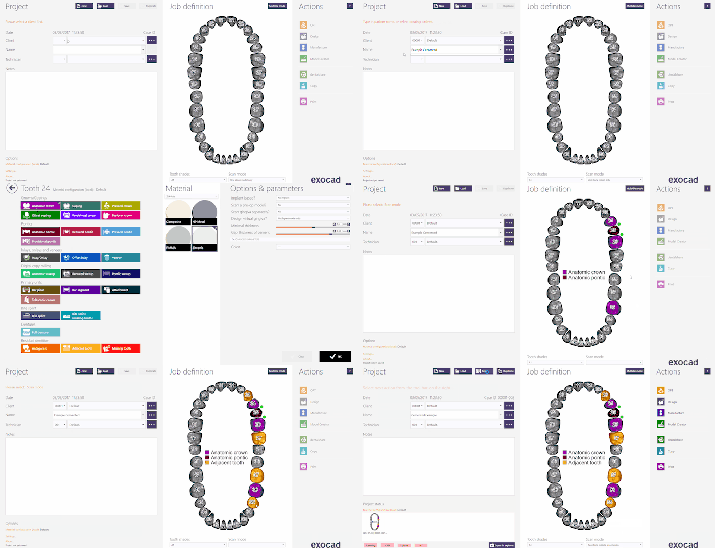
プロジェクト情報、設計する修復の種類、その他のパラメーターを入力します。この種類のプロジェクトでは、Scan Mode(スキャンモード)がTwo stone models in occlusion(咬合する2つの石膏模型)に設定されていることを確認して下さい。
Exocadでプロジェクトを作成する方法について詳しくは、Exocad Wiki!を参照して下さい。
今回のデモ用プロジェクトでは以下の通りプロジェクトを定義します。
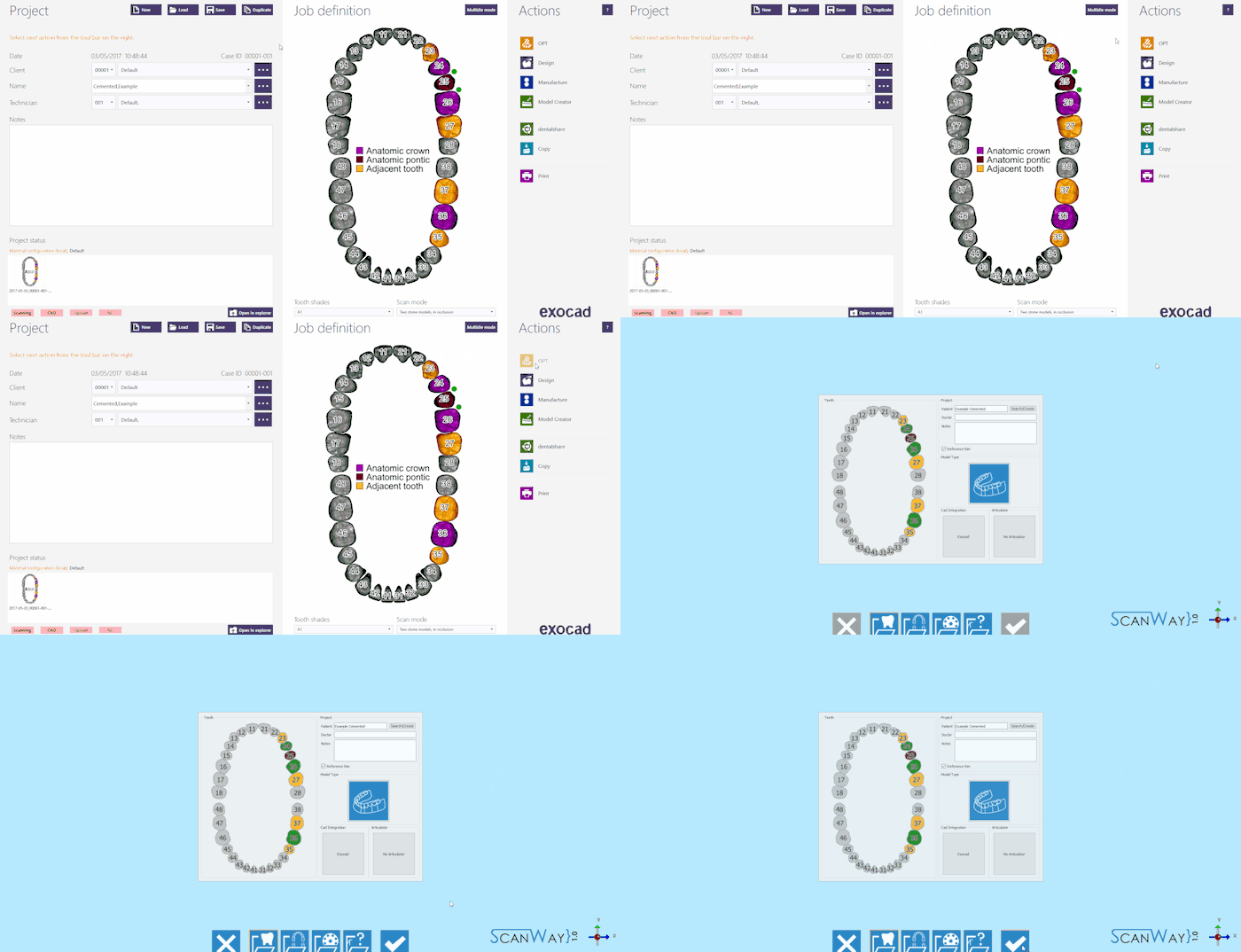
プロジェクトの定義が完了したら、Actions(アクション)セクションのOPTをクリックして、スキャンソフトウェアを起動します。
スキャンソフトウェアでは、Exocadで作成されたプロジェクトが最初に表示されます。プロジェクトが正しく定義されている場合は、確定ボタン ![]() をクリックします。
をクリックします。
ScanWayでプロジェクト定義を開始する
すべてのプロジェクトは、後で設計に使用するCADにかかわらず、スキャンソフトウェアでも定義できます。
デスクトップのScanWayアイコンをダブルクリックして、スキャンソフトウェアを起動します。ようこそページが開きます。プロジェクトを作成するには、最初のアイコンをクリックします。
プロジェクトの定義方法について詳しくは、新規プロジェクトの作成のページを参照して下さい。
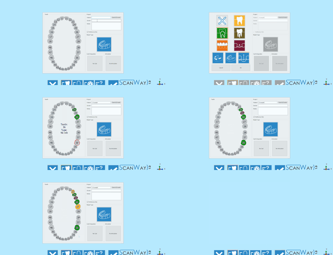
今回のデモ用プロジェクトでは以下の通り定義します。
どちらの方法でプロジェクトを定義しても、同じウィザードに進みます。ここからは、このウィザードに従っていきます。
ステップ1: 咬合器スキャン
両顎を持つように設定されたすべてのプロジェクトの最初のステップは、咬合器スキャンです。
咬合器スキャンと言っても、必ず咬合器をスキャンする必要はありません。このスキャンでは、専用サポート上で咬合器をスキャンするか、またはモデルホルダーで2つのモデルを咬合させてスキャンします。
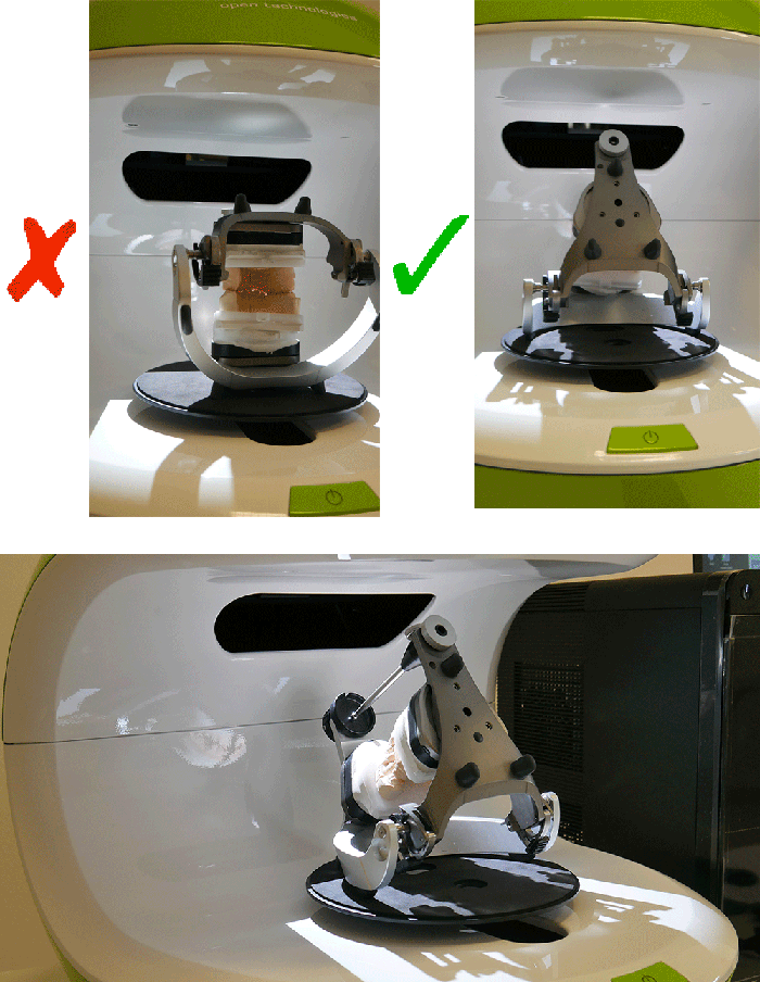
ユーザーが咬合器をスキャンする必要がある場合は、後ろへ傾けることをおすすめします。こうすることで、できるだけ多くの情報を得ることができるようになります。傾けることができない咬合器もあるので、その場合は不要です。
スキャンインターフェースのライブビューでは、咬合器がまっすぐ置かれていると、咬合状態を正確に取得するのが難しくなることが実際に確認できます。
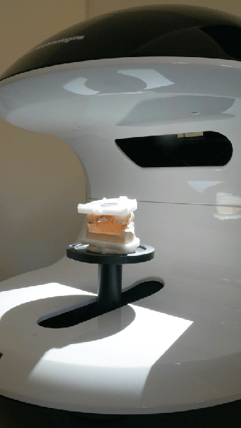
一方、前述のように、咬合させた2つのモデルを輪ゴムやワックスで固定して、通常のモデルホルダー上でスキャンすることも可能です。
オブジェクトをスキャナーに置いたら(咬合器を使って、またはモデルを重ねて)、スキャンボタン![]() でスキャンを開始できます。スキャンが終了すると、結果が表示されます。
でスキャンを開始できます。スキャンが終了すると、結果が表示されます。
利用可能なその他の機能については、スキャンインターフェースのページを参照して下さい。
ステップ2: 下顎
両顎を持つように設定されたすべてのプロジェクトでは、2番目のステップとして下顎モデルをスキャンします。咬合器を除くすべてのステップには、2つのサブステップ(実際のスキャンと、取得された画像の編集)があります。
スキャンステップ
下顎モデルをモデルホルダーに置き、スキャンボタン![]() をクリックします。スキャンが完了すると、結果が表示されます。
をクリックします。スキャンが完了すると、結果が表示されます。
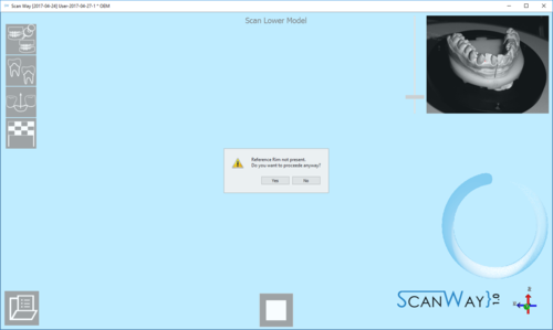
このスキャンはリファレンスリムを使って実行します。ユーザーがモデル、ダイ、またはマーカーのスキャンを起動する際、ソフトウェアでリファレンスリムが使用されていないことが検出されると、以下のメッセージが表示されます。
ユーザーは、スキャンをキャンセルしてモデルホルダーにリファレンスリムを設置し、新しいスキャンを開始するか、リファレンスリムなしでスキャンを続行するかを決めることができます。リファレンスリムについて詳しくは、付属品のページを参照して下さい。
編集ステップ
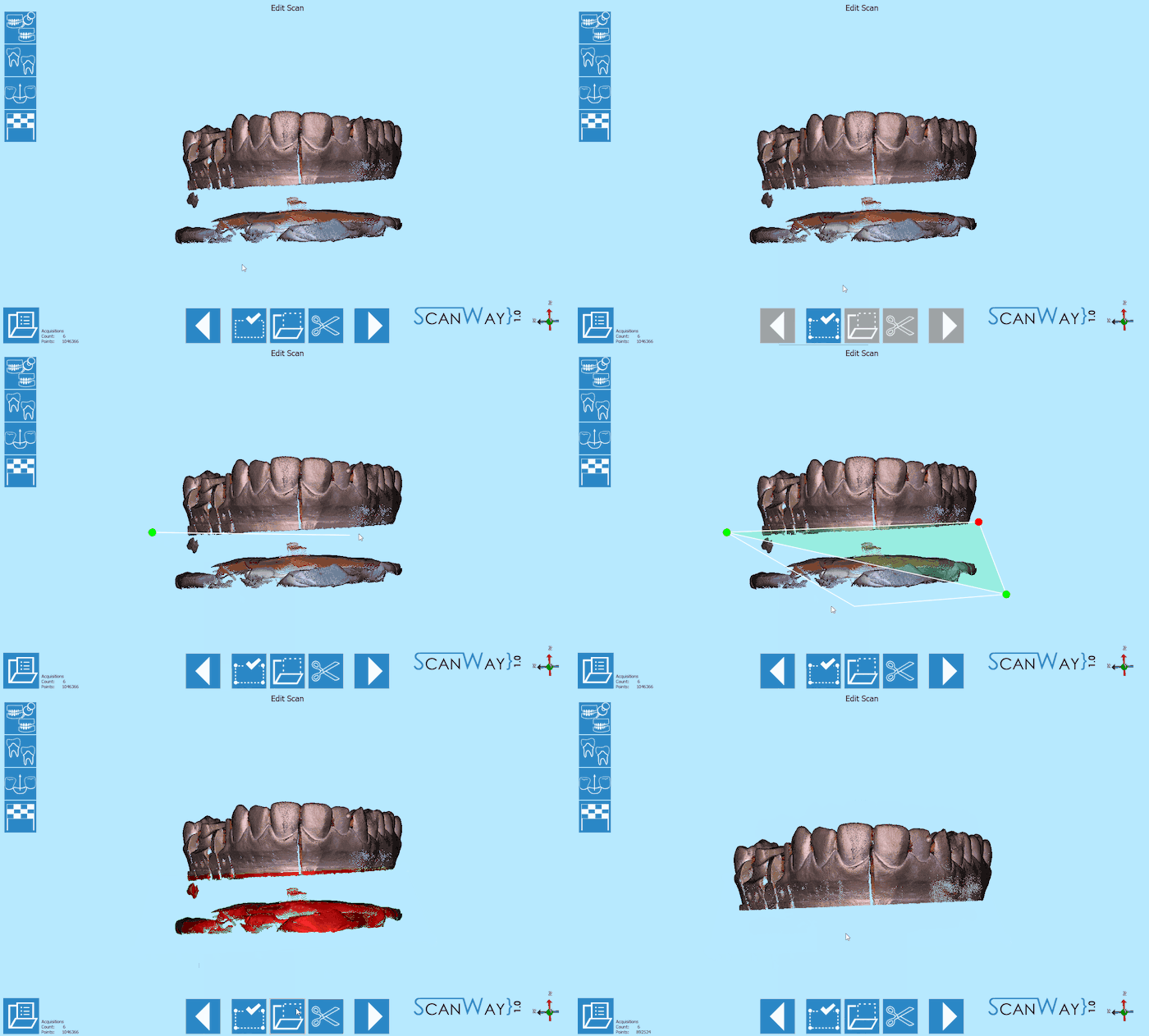
このステップでは、取得した画像を編集できます。このステップで利用できるオプションについて詳しくは、編集ツールのページを参照して下さい。
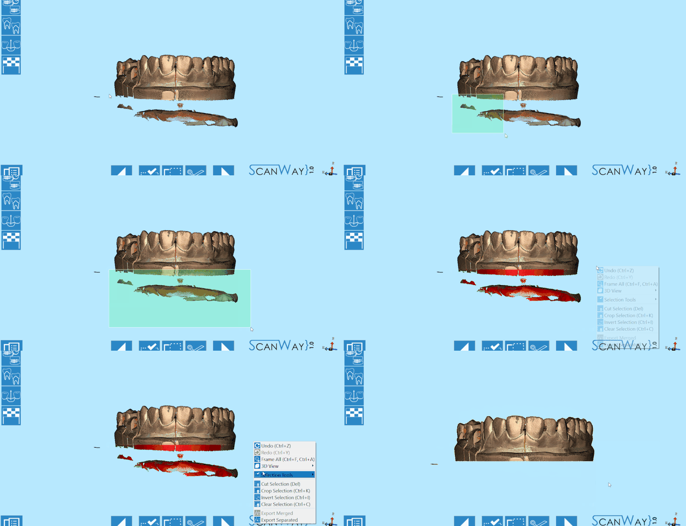
この段階の画像は編集したりトリミングしたりできます。ただし、この段階では画像に対してあまり大きな編集を行ったり、多くの情報を切り取ったりしないことが重要です。このような編集により、オブジェクトとリファレンスモデルとの自動アライメントの計算が困難になる場合があります。
画像の編集は、選択ツールを使って実行できます。
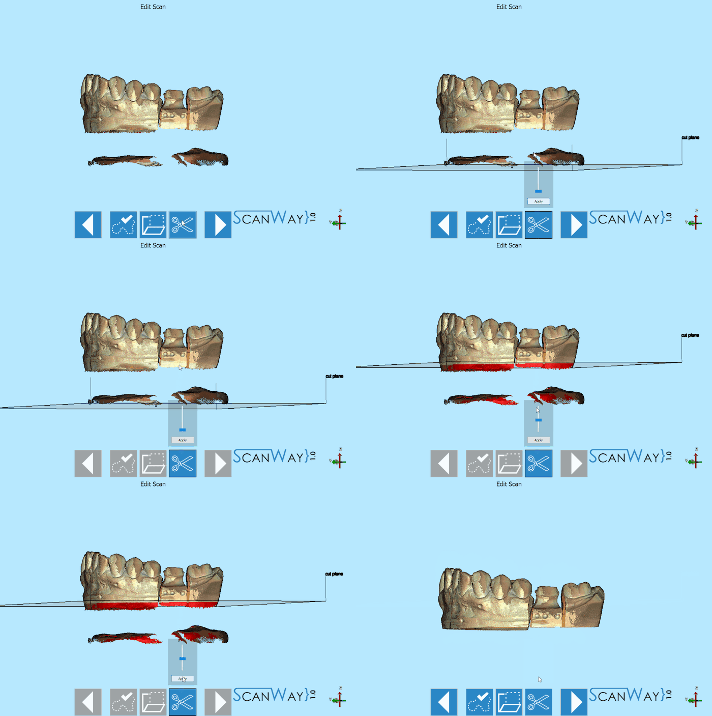
一方、トリミングはベースカットツールを使用すると非常に簡単に行えます。
適切な結果が取得できたら、![]() をクリックして次のステップに進みます。
をクリックして次のステップに進みます。
ステップ3: 上顎モデル
上顎モデルのスキャンでは、下顎モデルと同じように、2つのステップを実行する必要があります。
スキャンステップ
上顎モデルをモデルホルダーに置き、スキャンボタン![]() をクリックします。スキャンが完了すると、結果が表示されます。
をクリックします。スキャンが完了すると、結果が表示されます。
リファレンスリムがモデルホルダーに置かれていない場合は、ここでも前述のメッセージが表示されます。
編集ステップ
上顎モデルもまだ編集可能です。ここでは、別の選択ツールを使って画像を編集します。
適切な結果が取得できたら、![]() をクリックして次の手順に進みます。
をクリックして次の手順に進みます。
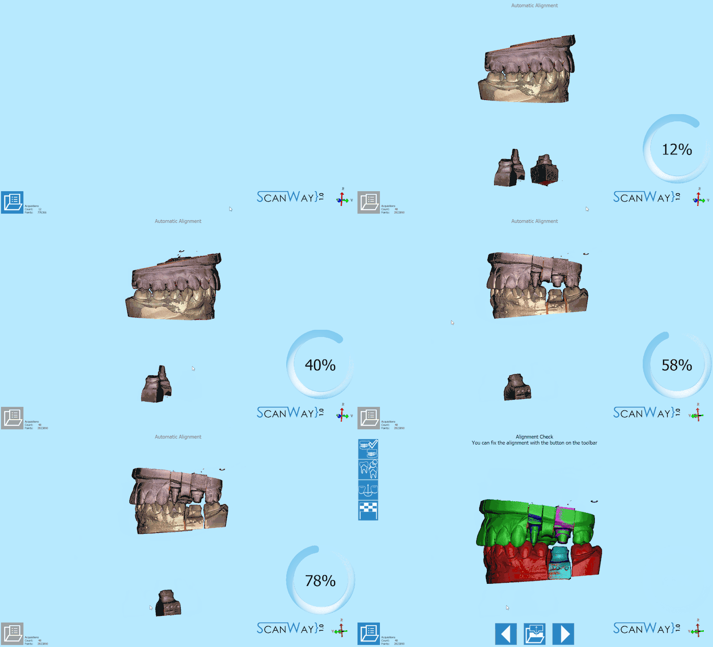
保存とアライメント
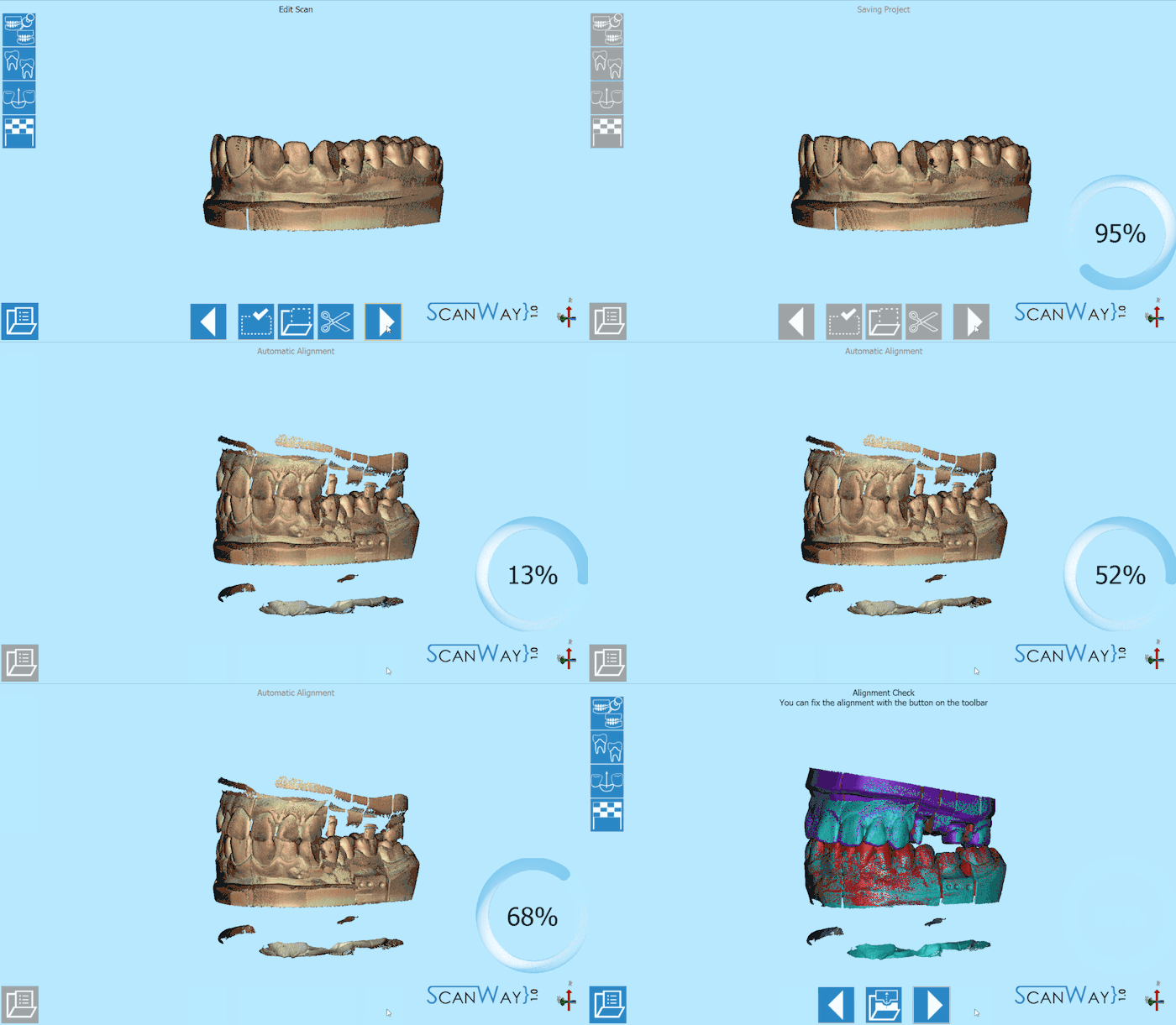
![]() ボタンを押すと、ソフトウェアではすぐに保存が実行され、スキャンされたアイテムがそれぞれのリファレンスに対して自動でアライメントされます。
ボタンを押すと、ソフトウェアではすぐに保存が実行され、スキャンされたアイテムがそれぞれのリファレンスに対して自動でアライメントされます。
自動アライメントおよび手動による手順については、アライメントインターフェースのページを参照して下さい。
ステップ4: ダイのスキャン
ダイのスキャンに必要なステップは、ユーザーが選択したスキャン方法(マルチダイプレートを使用するか、カスタム設定を使用するか)によって異なります。
マルチダイ使用時
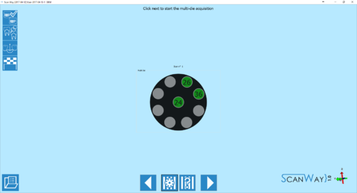
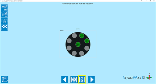
デフォルトではこの方法が適用されています。この場合、マルチダイプレート上でソフトウェアが指示する位置にユーザーがダイを置いていきます。これにより各ダイが直ちに識別されます。
- 定義
- 前述の通り、マルチダイプレートのダイの位置はソフトウェアによって事前に認識されています。
マルチダイの順番はユニバーサル方式に基づいており、最初の片顎の最後の部品から開始して、時計回りの順番になっています。これにより、中央に配置するダイは、常に最初の片顎の最後の部品に最も近いものとなります。
ダイが9個を超える場合、追加の定義ステップが表示されます。
![]() をクリックして、マルチダイスキャンの編集ステップに進みます。
をクリックして、マルチダイスキャンの編集ステップに進みます。
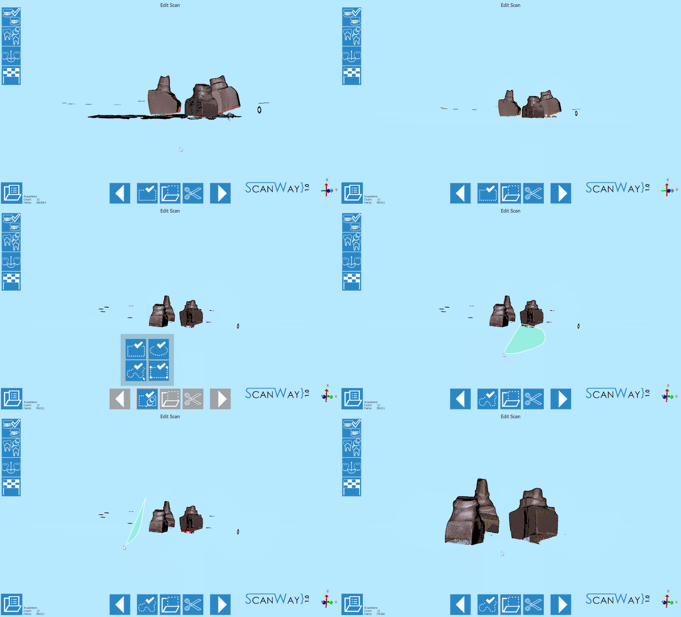
- 編集
- 編集ステップでは、以前のステップで表示されたものと同じツールが利用できます。今回のケースでは、2つ以上のツールを適用する必要があります。
適切な結果が取得できたら、![]() をクリックして次のステップに進みます。
をクリックして次のステップに進みます。
- アライメント
- 編集が終わったら、ダイがリファレンスに対してアライメントされ、結果がモニター上に表示されます。アライメントを変更したり、修正したり、やり直したりする場合は、アライメントインターフェースのページを参照して下さい。
カスタム設定(マルチダイなし)
モデルベース上のダイをスキャンする必要がある場合など、カスタムの順番でダイをスキャンすることもできます。カスタム設定による定義を行うには、ソフトウェアでマルチダイの定義が表示されたときに ![]() アイコンをクリックします。
アイコンをクリックします。
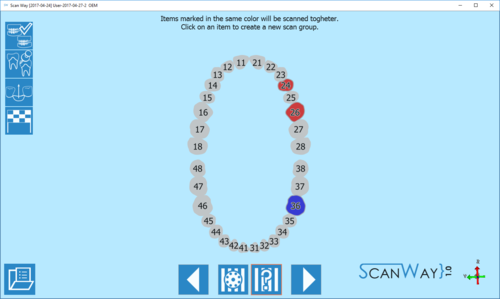
- スキャン
- 作成したスキャングループの数によって、1つまたは複数のスキャンステップが設定されます。
まずは、ダイをスキャナーに入れて、最初のグループのアイテムを取得する必要があります。
リマインダーとして、同時にスキャンされるアイテムがウインドウ右側のライブビューの下にマークされて表示されます。
次に、2つ目のグループに選択されたアイテムを入れるよう求められます。2つ目のスキャンは個別のダイなので、右側にリマインダーは表示されません。![]() をクリックして続行します。
をクリックして続行します。
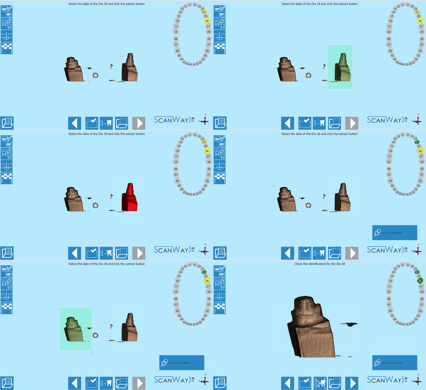
- ダイの識別
- スキャングループに複数のアイテムがある場合、ユーザーは各ダイをそれぞれ正しく識別するよう求められます。
このステップはスキャンステップの間で発生します。ダイの識別について詳しくは、スキャンインターフェースのページを参照して下さい。 をクリックして続行します。
- アライメント
- 編集または識別されると、ダイはリファレンスに対してアライメントされ、結果がモニター上に表示されます。アライメントを変更したり、修正したり、やり直したりする場合は、アライメントインターフェースのページを参照して下さい。
ステップ5: 健全部分とポンティック
この段階でプロジェクトのスキャンは終わっていますが、ユーザーが健全部分やポンティックを再スキャンしたい場合もあります。実際、このステップは、スキャンされたリファレンスモデルのスキャンから、個別にスキャンした部分(今回の場合はダイ)をトリミングしたものです。 最初のモデルスキャンで、健全部分の接触点が正しく認識されないことがあり、その場合ユーザーはモデルを再スキャンする必要があります。そうでない場合は、![]() をクリックして続行します。
をクリックして続行します。
その後、ソフトウェアには詳しい編集ステップが表示されるので、ユーザーは健全部分の画像を編集できます。編集ステップでは、前述の説明に従って下さい。
ステップ6: メッシュ生成およびエクスポート
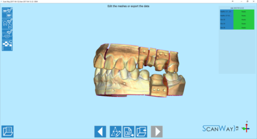
この時点で、ソフトウェアは自動的にメッシュ生成を開始します。メッシュは編集したり、個別にエクスポートしたり、画像としてエクスポートしたりできます。メッシュの編集について詳しくは、メッシュツールのページを参照して下さい。
エクスポートボタン ![]() をクリックして、CADにエクスポートします。
をクリックして、CADにエクスポートします。
プロジェクトをExocadから開始した場合、CADが自動的に開き、すぐに設計を始めることができます。それ以外の場合は、ファイルをエクスポートする方法を選択するよう求められます。
