Difference between revisions of "ExamplesQuadrant/ja"
(Created page with "{{Inline button|nextAction.png}} をクリックして、ウィザードの2つ目のステップに進みます。") |
(Created page with "==ステップ2: クオドラントスキャン==") |
||
| Line 55: | Line 55: | ||
{{Inline button|nextAction.png}} をクリックして、ウィザードの2つ目のステップに進みます。 | {{Inline button|nextAction.png}} をクリックして、ウィザードの2つ目のステップに進みます。 | ||
| − | == | + | ==ステップ2: クオドラントスキャン== |
This step develops in the usual phases. | This step develops in the usual phases. | ||
Revision as of 10:56, 24 September 2017
このページでは、咬合する2つの1/4顎モデルと3つのダイを、オープンテクノロジーのクオドラントモジュールを使ってスキャンする例を、ウィザードに従って説明します。
このモジュールでは、1/4顎のモデルと最大4つの歯型を、2ステップで定義されたプロジェクトでスキャンできます。これでスキャン時間が半分になります。
これは追加ライセンス用モジュールです。詳細はディーラーにお問い合わせ下さい
Contents
Exocadでプロジェクト定義を開始する
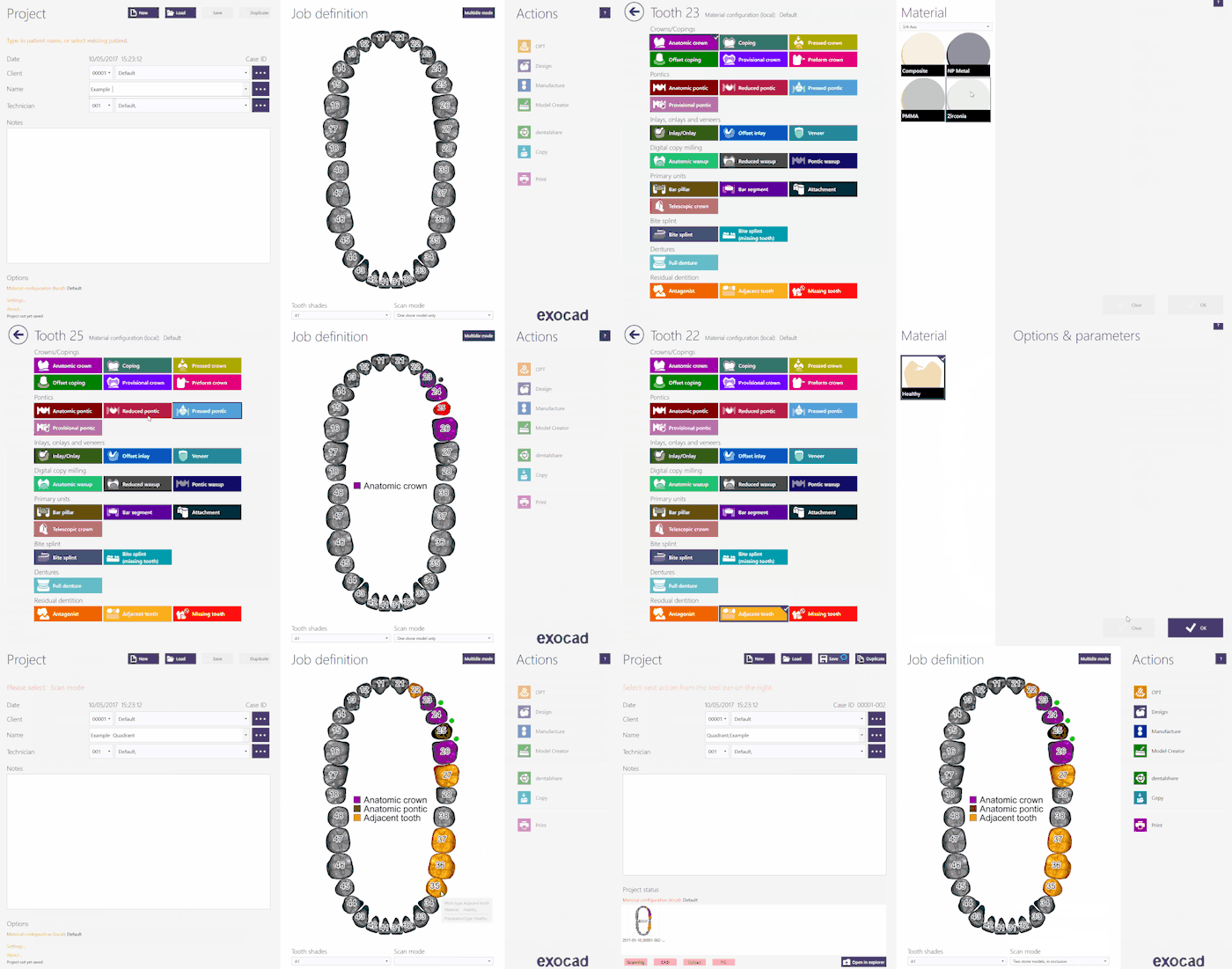
このプロジェクトをExocadで作成するには、デスクトップでDentalDBアイコンをクリックします。プロジェクトマネージャーが開きます。
プロジェクト情報、設計する修復の種類、その他のパラメーターを入力します。この種類のプロジェクトでは、Scan Mode(スキャンモード)がTwo stone models in occlusion(咬合する2つの石膏模型)に設定されていることを確認して下さい。モデルのタイプは後で指定され、それにより正しいウィザードが起動します。
Exocadでプロジェクトを作成する方法について詳しくは、Exocad Wiki!を参照して下さい。
今回のデモ用プロジェクトでは以下の通りプロジェクトを定義します。
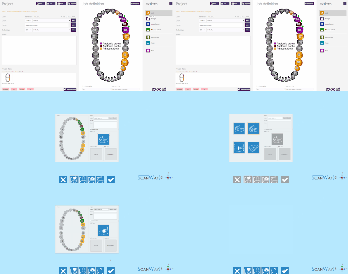
プロジェクトが定義されたら、アクションセクションでOPTをクリックすると、スキャンソフトウェアが起動します。
スキャンソフトウェアでは、まずExocadで作成されたプロジェクトが表示されます。
正しいウィザードを有効にするには、Model Type(モデルタイプ)アイコンをクリックして、![]() オプションを選択します。
オプションを選択します。
確定ボタン ![]() をクリックすると、変更内容が保存され、プロジェクトが開始されます。
をクリックすると、変更内容が保存され、プロジェクトが開始されます。
ScanWayでプロジェクト定義を開始する
すべてのプロジェクトは、後で設計に使用するCADにかかわらず、スキャンソフトウェアでも定義できます。
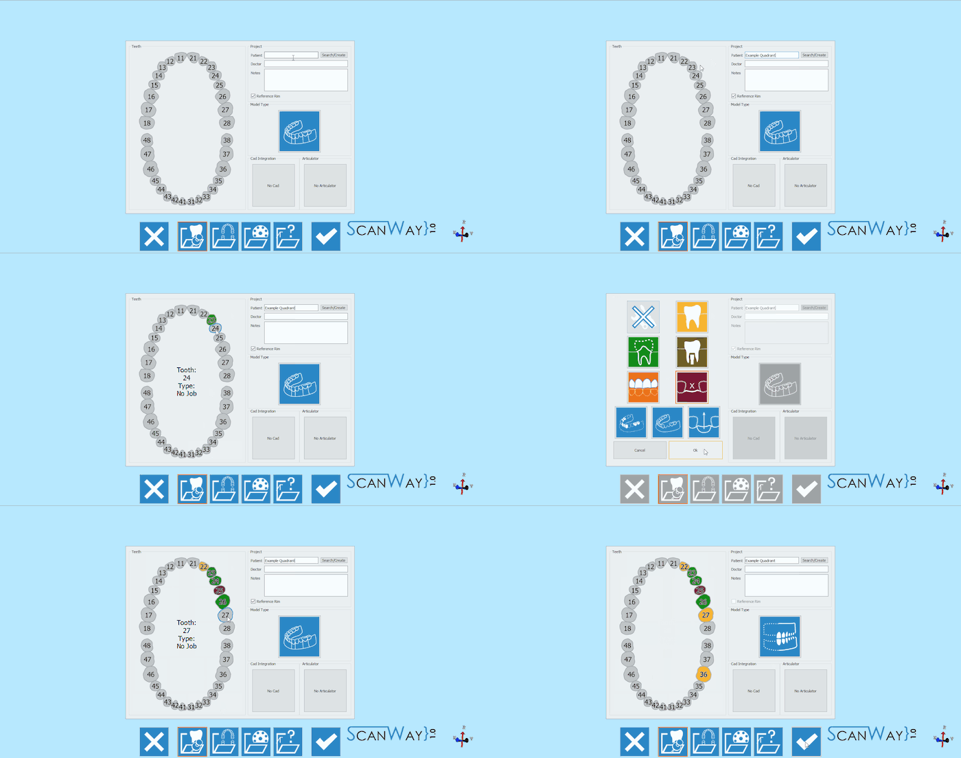
デスクトップのScanWayアイコンをダブルクリックして、スキャンソフトウェアを起動します。ようこそページが開きます。プロジェクトを作成するには、最初のアイコンをクリックします。
プロジェクトの定義方法について詳しくは、新規プロジェクトの作成のページを参照して下さい。
今回のデモ用プロジェクトでは以下の通り定義します。
どちらの方法でプロジェクトを定義しても、同じウィザードに進みます。ここからは、このウィザードに従っていきます。
ステップ1: 咬合器スキャン
この場合の咬合器とは、クオドラントトレーオクルーザーを指しており、これを通常のモデルホルダー上で直接スキャンできます。
モデルホルダーにオクルーザーを置く方法は自由に決めることができますが、以下の例を参考にして決定して下さい。
オブジェクトをスキャナーに置いたら(咬合器を使って、またはモデルを重ねて)、スキャンボタン![]() でスキャンを開始できます。スキャンが終了すると、結果が表示されます。
でスキャンを開始できます。スキャンが終了すると、結果が表示されます。
利用可能なその他の機能については、スキャンインターフェースのページを参照して下さい。
ステップ2: クオドラントスキャン
This step develops in the usual phases.
Scan
For this step, all the elements need to be positioned as marked by the software in the Quadrant holder.
Click the Scan Button![]() to start the scan. Once the scan is finished the result will be shown.
to start the scan. Once the scan is finished the result will be shown.
Click ![]() to access the edit step.
to access the edit step.
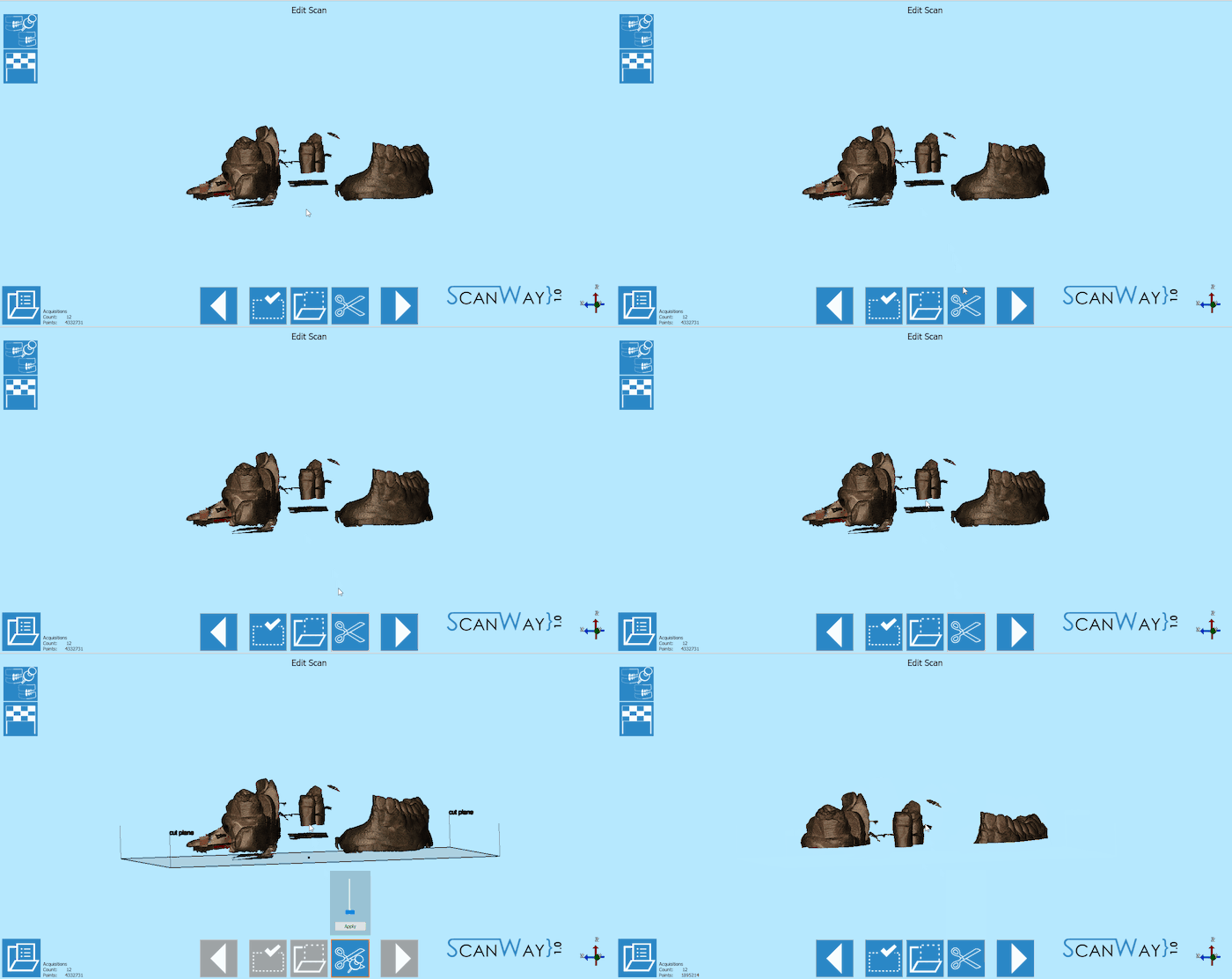
Edit
In this case, the image has been trimmed using the base cut tool and clicking on the apply button.
BE CAREFUL NOT TO TRIM TOO MUCH, AS TO DO SO THE SOFTWARE MIGHT HAVE ISSUES DURING THE AUTOMATIC ALIGNMENT
Click ![]() to access the alignment phase.
to access the alignment phase.
Alignment
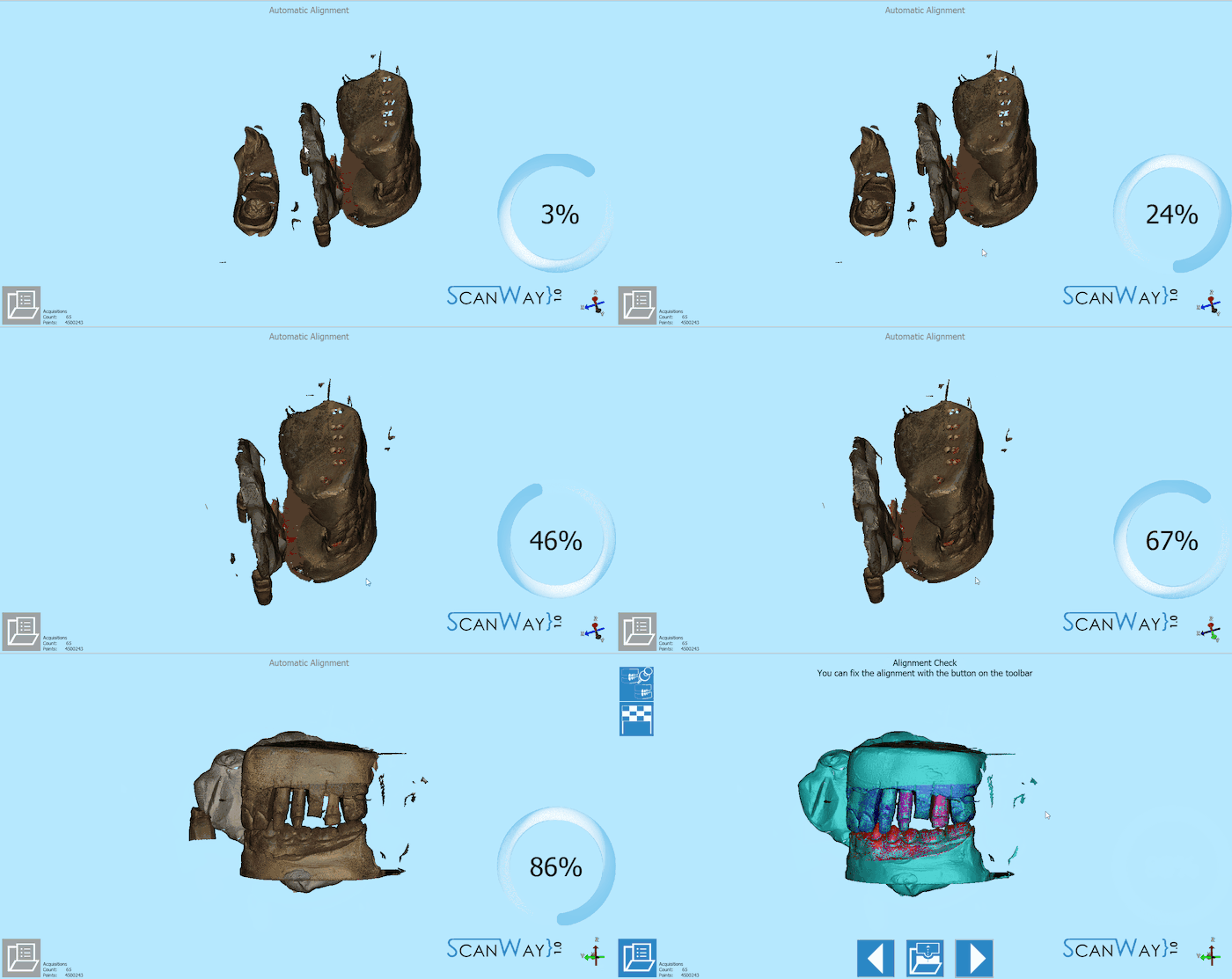
As for all scanned items, the software tries to align all the images to their reference. In this case the reference for all the scanned items is the articulator scan.
At the end of the alignment the results are shown. To learn more on the automatic alignment and the manual procedure visit our Alignment Interface page.
Click ![]() to access the last step of the wizard.
to access the last step of the wizard.
Step 3: Mesh Generation and Export
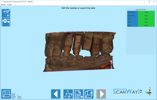
At this point the software immediately starts mesh generation. The meshes can be edited and exported individually or as a unique image. To learn more about mesh editing visit our Mesh Tools page.
Click on the Export Button ![]() to export to CAD.
to export to CAD.
If the project has been started from Exocad, the CAD will automatically open and the design can be started immediately. Otherwise the software will ask the user how to export the file.
