Example: Multidie
このページでは、同じマルチダイプレートで異なる患者のダイをスキャンする例を、ウィザードに従って説明します。
Contents
Exocadでプロジェクト定義を開始する
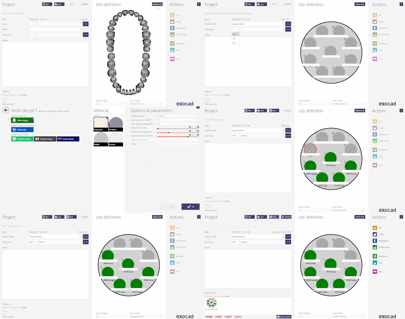
このプロジェクトをExocadで作成するには、デスクトップでDentalDBアイコンをクリックします。プロジェクトマネージャーが開きます。Multi Die(マルチダイ)をクリックして、プロジェクト定義パネルを開きます。
Exocadでプロジェクトを作成する方法について詳しくは、Exocad Wiki!を参照して下さい。
今回のデモ用プロジェクトでは以下の通りプロジェクトを定義します。
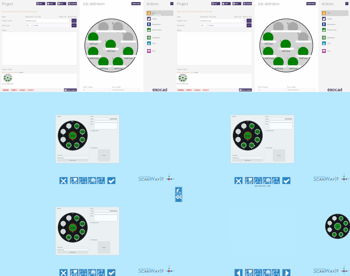
プロジェクトの定義が完了したら、Actions(アクション)セクションのOPTをクリックして、スキャンソフトウェアを起動します。
スキャンソフトウェアでは、Exocadで作成されたプロジェクトが最初に表示されます。プロジェクトが正しく定義されている場合は、確定ボタン ![]() をクリックします。
をクリックします。
ScanWayでプロジェクト定義を開始する
All projects can be defined in the scanning software as well, regardless the CAD that will be later on used to design.
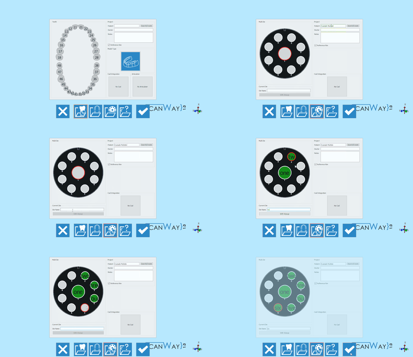
Launch the scanning software double-clicking on the ScanWay icon on your desktop. The Welcome Page will open; to create the project click on the first icon.
For detailed information on how to define a project visit the specific page: Create a New Project.
Here is the definition of our demo project:
Both the project definitions described lead to the same wizard, which will be now followed step by step.
Step 1: Multidie Scan
This is the only scan step for this kind of project. As usual, this scan steps is divided into substeps.
Scan Step
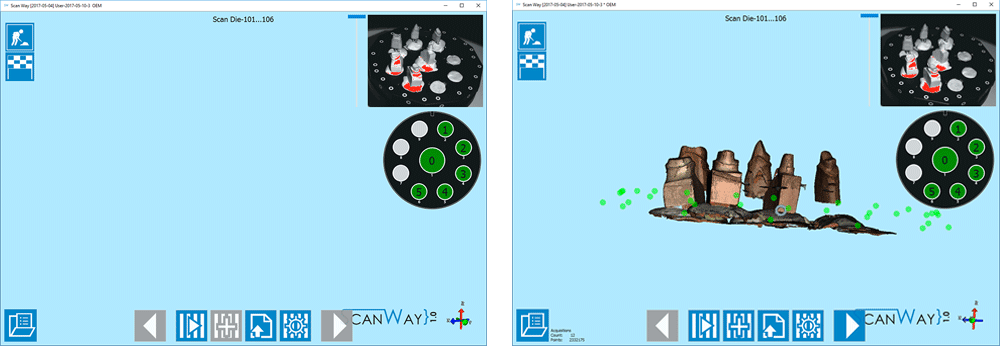
Place the dies on the multidie plate as prompted by the scanner and click the Scan Button![]() . Once the scan is finished the result will be shown.
. Once the scan is finished the result will be shown.
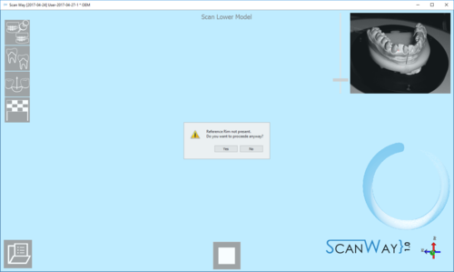
This scan has been performed with the Reference Rim. Everytime the user launches a scan for models, dies or markers, if the software recognises that the reference rim has not been used the following message shows.
The user can therefore decide whether to cancel the scan, put the reference rim on the model holder and start a new scan, or to scan without using the reference rim. For information on the reference rim visit the Accessories page.
Click ![]() to access the second part of the step.
to access the second part of the step.
Edit Step
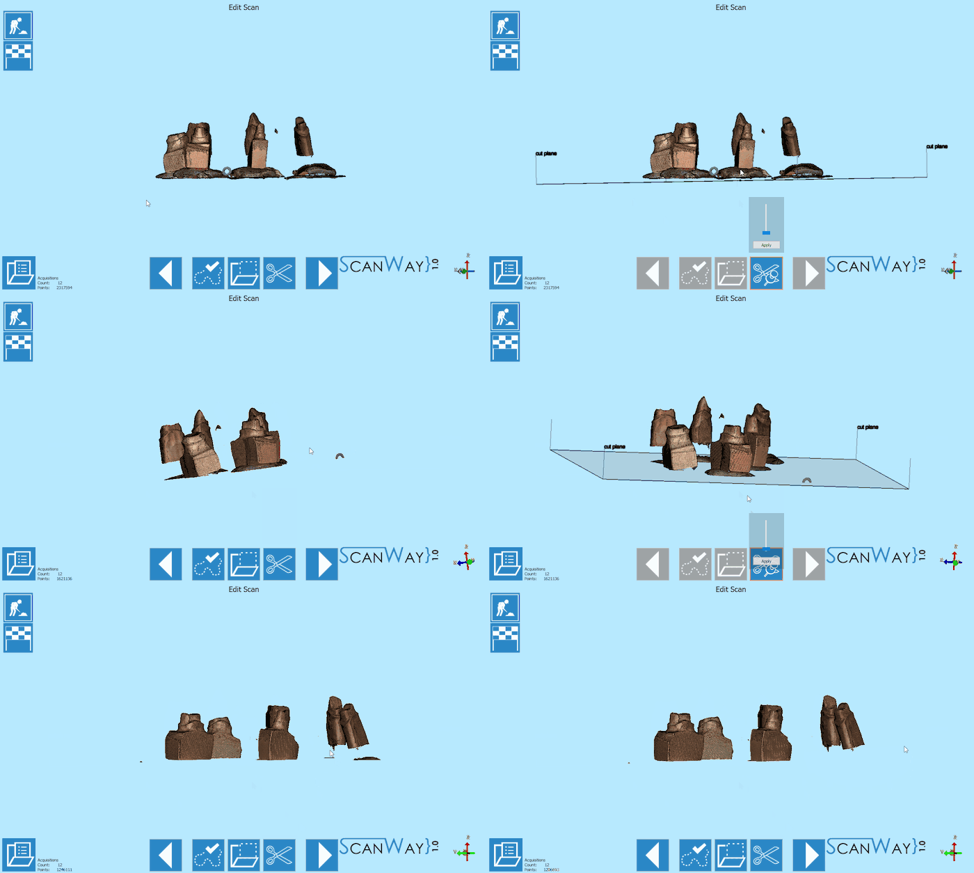
This step allows to edit the aquired image; for detailed information on all the available options in this step visit the Edit Tools page.
The image at this step can be both edited or trimmed. In this case, various tools have been used.
When you are satisfied with the result click ![]() to access the next wizard step.
to access the next wizard step.
Step 6: Mesh Generation and Export
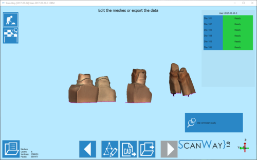
At this point the software immediately starts mesh generation. The meshes can be edited and exported individually or as a unique image. To learn more about mesh editing visit our Mesh Tools page.
Click on the Export Button ![]() to export to CAD.
to export to CAD.
If the project has been started from Exocad, the CAD will automatically open and the design can be started immediately. Otherwise the software will ask the user how to export the file.
