Example: Implants
このページでは、4つのインプラントとシリコンの歯肉部分のある1つのモデルをスキャンする例を、ウィザードに従って説明します。
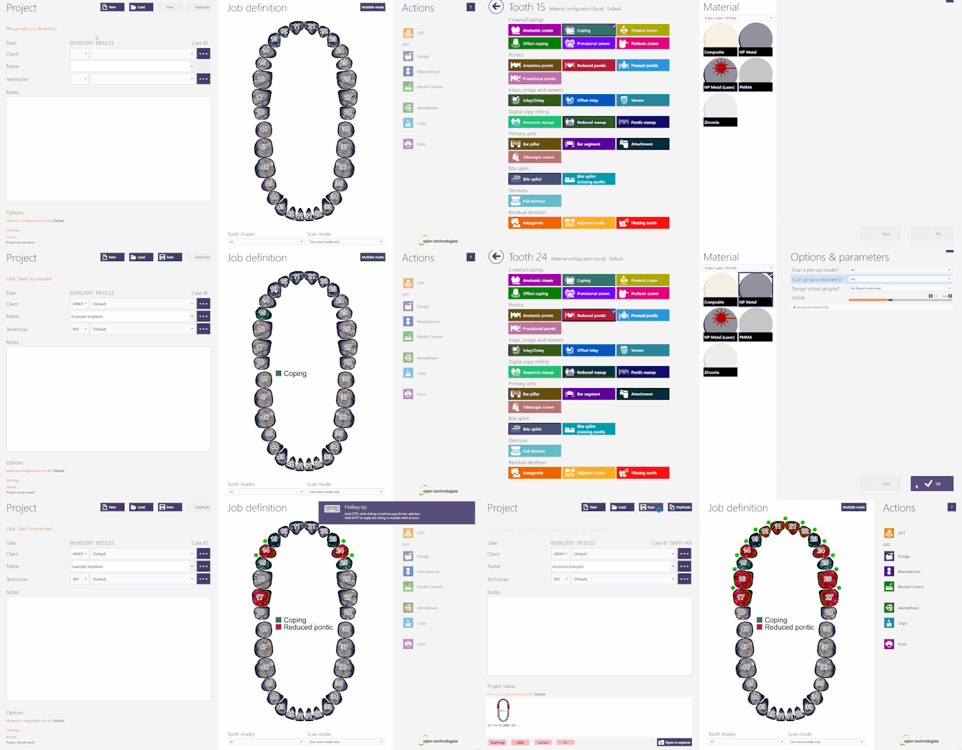
このプロジェクトをExocadで作成するには、デスクトップでDentalDBアイコンをクリックします。プロジェクトマネージャーが開きます。
プロジェクト情報、設計する修復の種類、その他のパラメーターを入力します。この種類のプロジェクトでは、Implant type(インプラントタイプ)およびSeparated Gingiva(歯肉分離)を選択していることを確認して下さい。
Exocadでプロジェクトを作成する方法について詳しくは、Exocad Wiki!を参照して下さい。
今回のデモ用プロジェクトでは以下の通りプロジェクトを定義します。
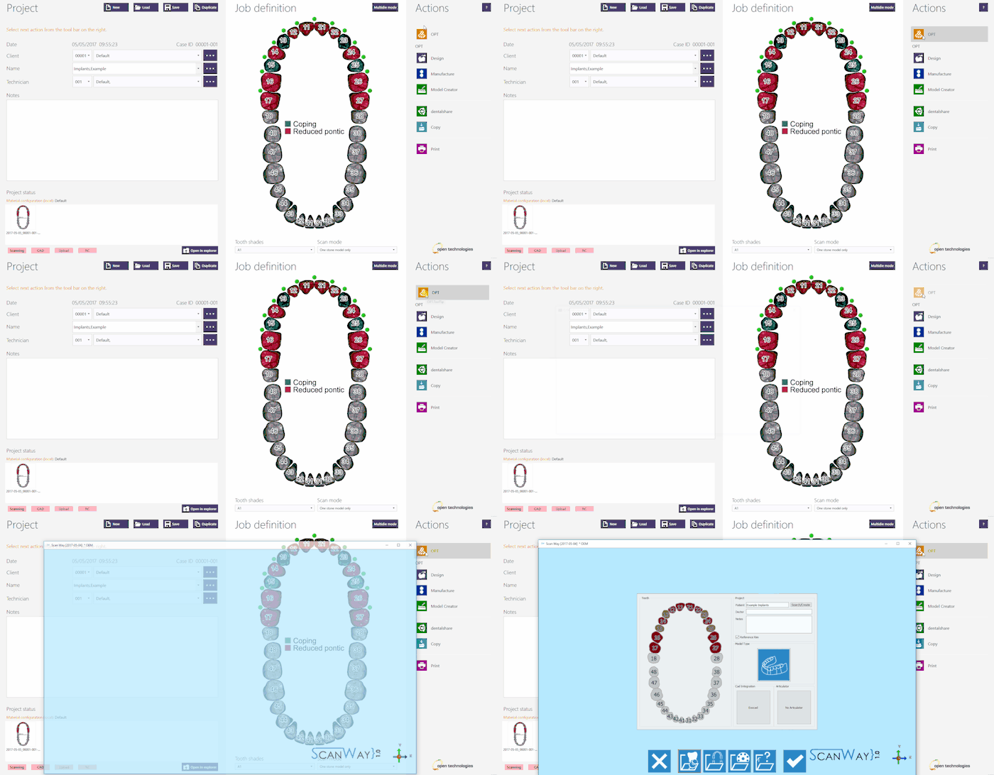
プロジェクトの定義が完了したら、Actions(アクション)セクションのOPTをクリックして、スキャンソフトウェアを起動します。
スキャンソフトウェアでは、Exocadで作成されたプロジェクトが最初に表示されます。プロジェクトが正しく定義されている場合は、確定ボタン ![]() をクリックします。
をクリックします。
Contents
ScanWayでプロジェクト定義を開始する
すべてのプロジェクトはスキャンソフトウェアでも定義できます。これは、後で設計に使用するCADとは関係ありません。
デスクトップのScanWayアイコンをダブルクリックして、スキャンソフトウェアを起動します。ようこそページが開きます。プロジェクトを作成するには、最初のアイコンをクリックします。
プロジェクトの定義方法について詳しくは、新規プロジェクトの作成のページを参照して下さい。
今回のデモ用プロジェクトでは以下の通り定義します。
どちらの方法でプロジェクトを定義しても、同じウィザードに進みます。ここからは、このウィザードに従っていきます。
手順1: 上顎モデル
定義されたプロジェクトには対顎のモデルがないため、まずは上顎モデルをスキャンする必要があります。これは、その他すべてのスキャンを配置するときの参照点となります。
このプロセスには、以下の2つの手順があります。
スキャン手順
上顎モデルをモデルホルダーに設置し、スキャンボタン をクリックします。
この段階で必要なのは石膏模型のみです。歯肉の部分、マーカー、その他の付属するオブジェクトを忘れずに取り外して下さい。
スキャンが完了すると、結果が表示されます。
編集手順
この手順では、取得した画像を編集できます。この手順で利用できるオプションについて詳しくは、編集ツールのページを参照して下さい。
この段階の画像は編集したりトリミングしたりできます。ただし、この段階では画像に対してあまり大きな編集を行ったり、多くの情報を切り取ったりしないことが重要です。このような編集により、オブジェクトと参照モデルの自動アライメントの計算が困難になる場合があります。
以下はベースカットツールを使ったトリミング方法の例で、画像をダブルクリックして不要なパーツを取り除いています。
手順2: マーカー
この手順では、ユーザーがマーカーまたはスキャンボディをスキャンする必要があります。これは、CADソフトウェアでの形状寸法とインプラントのスクリューチャネルの正確な位置のマーキングに使用されます。
マーカーのスキャンは複数の手順で実行します。
Definition
It is not necessary to have one marker for each implant on the model, since the markers can be scanned in different groups. To demonstrate this possibility, the 4 markers that need to be scanned for this project have been divided into two scanning groups, as follows:
Click to access the scan step for the first group.
First Group
- Scan
- Depending on the number of scan groups created, the software will propose one or more scanning steps.
First, the software requires the user to insert the markers screwed on top of the model in the scanner and acquire the items of the first group.
As a reminder, it marks the items to be scanned together on the right of the window, under the live view.
Place the model with the selected markers on the model holder and click the Scan Button . Once the scan is finished the result will be shown.
Click to access the edit step.
- Edit
- Follows the edit step to clean or trim the image. This time the rectangular selection tool has been used and the cut action has been activated in the contextual menu.
Click to access the alignment step.
- Alignment
- The alignment for all scanned items is always automatic and it shows its results after the editing step.
To learn more on the automatic alignment and the manual procedure visit our Alignment Interface page.
- Marker Identification
- When a scan group has more than one item, the user will be asked to separate each marker from the others to correctly identify it.
To learn more on the identification of the dies visit the Scan Interface page.
Second group
- Scan
- Since in the project the markers have been divided into two groups, this is the last scan of the marker acquisition step.
As before, the software shows a reminder and marks the items to be scanned together on the right of the window, under the live view.
Place the model with the selected markers on the model holder and click the Scan Button . Once the scan is finished the result will be shown.
Click to access the edit step.
- Edit
- This image has been edited with the polygonal selection tool; the cut action has been activated in the contextual menu.
Click to access the alingment step.
- Alignment
- The alignment for all scanned items is always automatic and it shows its results after the editing step.
To learn more on the automatic alignment and the manual procedure visit our Alignment Interface page.
- Marker Identification
- When a scan group has more than one item, the user will be asked to separate each marker from the others to correctly identify it.
To learn more on the identification of the dies visit the Scan Interface page.
Step 3: Gingiva
If in the project has been specified the presence of a silicon gingiva, that can be separated from the model, the software will ask the user to scan it on top of the reference model.
Also this step develops in different phases.
Scan Step
Place the upper model with the gingiva on the model holder and click the Scan Button .
Once the scan is finished the result will be shown.
Edit Step
This item has been trimmed using the rectangular selection tool; the selected part has been deleted by pushing the DELETE (DEL) button on the keybord.
Automatic Alignment
As for the other items, the image of the gingiva aligns automatically to its reference (the upper model). The model part that matches the reference will then be removed automatically to keep only the actual gingiva part in mesh format.
Step 4: Healthy and Pontics
At this stage the project has been scanned, unless the user wants to rescan the healthy and pontics. In this case, since there are no healthy teeth there is no need to rescan.
Click to continue.
The software will then propose a further edit step to allow the user to modify the healthy image. Proceed in the edit step as previously explained.
Step 5: Marker Alignment
To serve their purpose, the markers need to be aligned to an implant library: a virtual, geometric, accurate representation of the scanbody that has been screwed to the stone analog to mark its position.
The alingment to the library can be perfomed either in the scanning software or in Exocad. Since the market of libraries and scanbodies is so diverse, it is possible that some libraries will not work in our system.
Here below the library selection performed for our demo case:
Immediately after, the user will be asked to align the STL of the Marker to the scanned items:
To learn more on how to select a library and align the scanbodies to it, visit the section Marker alignment of the page Alignment Interface.
Step 6: Mesh Generation and Export
At this point the software immediately starts mesh generation. The meshes can be edited and exported individually or as a unique image. To learn more about mesh editing visit our Mesh Tools page.
Click on the Export Button to export to CAD.
If the project has been started from Exocad, the CAD will automatically open and the design can be started immediately. Otherwise the software will ask the user how to export the file.

