Example: Quadrant Module
In questa pagina è mostrata e spiegata la procedura guidata da seguire per scansionare 2 modelli di emiarcate in occlusione con 3 impianti, utilizzando il modulo Concept Quad di Open Technologies.
Questo modulo permette di scansionare emiarcate con fino a 4 monconi, in un progetto a 2 fase predefinito che permette di risparmiare fino alla metà del tempo.
QUESTO E' UN MODULO OPTIONAL OPEN TECHNOLOGIES: CHIEDI AL TUO RIVENDITORE COME OTTENERLO!!
Contents
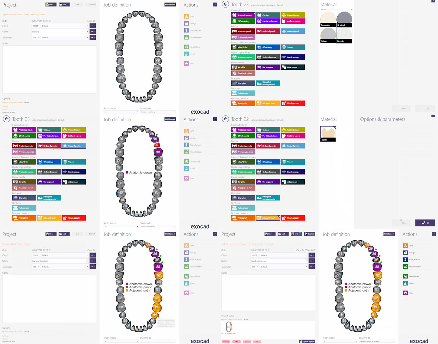
Definizione del progetto in Exocad
Per creare questo progetto in Exocad, cliccare sull'icona DentalDB sul desktop, aprendo così il Gestore Progetti.
Inserire le informazioni del progetto, il tipo di ricostruzione che dovrà essere modellata e i parametri aggiuntivi. Per questo tipo di progetto assicurarsi che la Modalità Scansione sia impostata su Due modelli in occlusione; il tipo di modello verrà specificato in seguito nel software per avviare la procedura guidata corretta.
For further information on how to create projects in Exocad, visit the specific page on the Exocad Wiki!
Here is the project definition for our demo project:
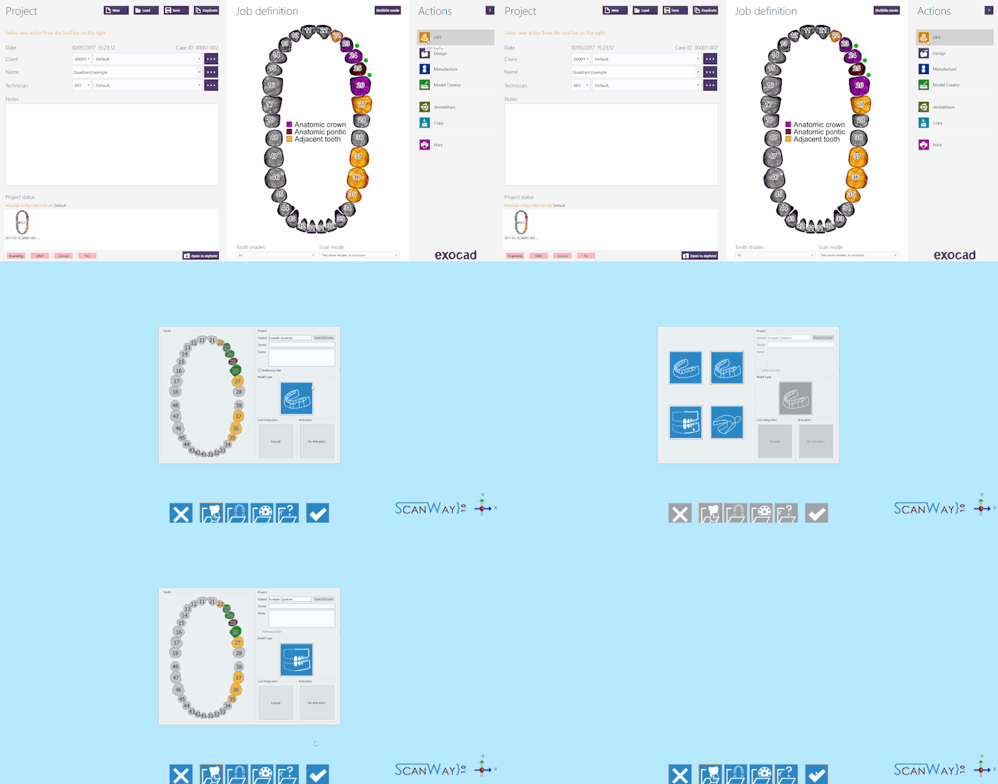
Once the project has been defined just click OPT in the Actions section to launch the scanning software.
The first thing the scanning software shows is the project created in Exocad.
In order to activate the correct wizard, click on the Model Type icon and select the ![]() option.
option.
Click the Accept button ![]() to save the changes and start the project.
to save the changes and start the project.
Project definition starting from ScanWay
All projects can be defined in the scanning software as well, regardless the CAD that will be later on used to design.
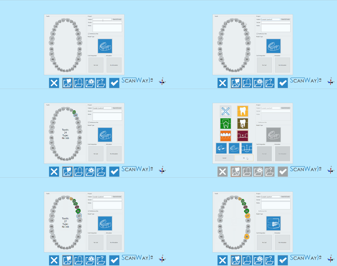
Launch the scanning software double-clicking on the ScanWay icon on your desktop. The Welcome Page will open; to create the project click on the first icon.
For detailed information on how to define a project visit the specific page: Create a New Project.
Here is the definition of our demo project:
Both the project definitions described lead to the same wizard, which will be now followed step by step.
Step 1: Articulator Scanning
In this case, for articulator, is meant the quadrant tray occlusor, which can be scanned directly on the normal model holder.
The user can decide freely how to place the occlusor on the model holder, here are our suggestions.
Once the objects have been placed in the scanner (either the articulator or the models one on top of the other), the scan can be started with the Scan Button![]() . Once the scan is finished the result will be shown.
. Once the scan is finished the result will be shown.
For further information on the other available functions check the Scan Interface page.
Click ![]() to access the second step of the wizard.
to access the second step of the wizard.
Step 2: Quadrant Scan
This step develops in the usual phases.
Scan
For this step, all the elements need to be positioned as marked by the software in the Quadrant holder.
Click the Scan Button![]() to start the scan. Once the scan is finished the result will be shown.
to start the scan. Once the scan is finished the result will be shown.
Click ![]() to access the edit step.
to access the edit step.
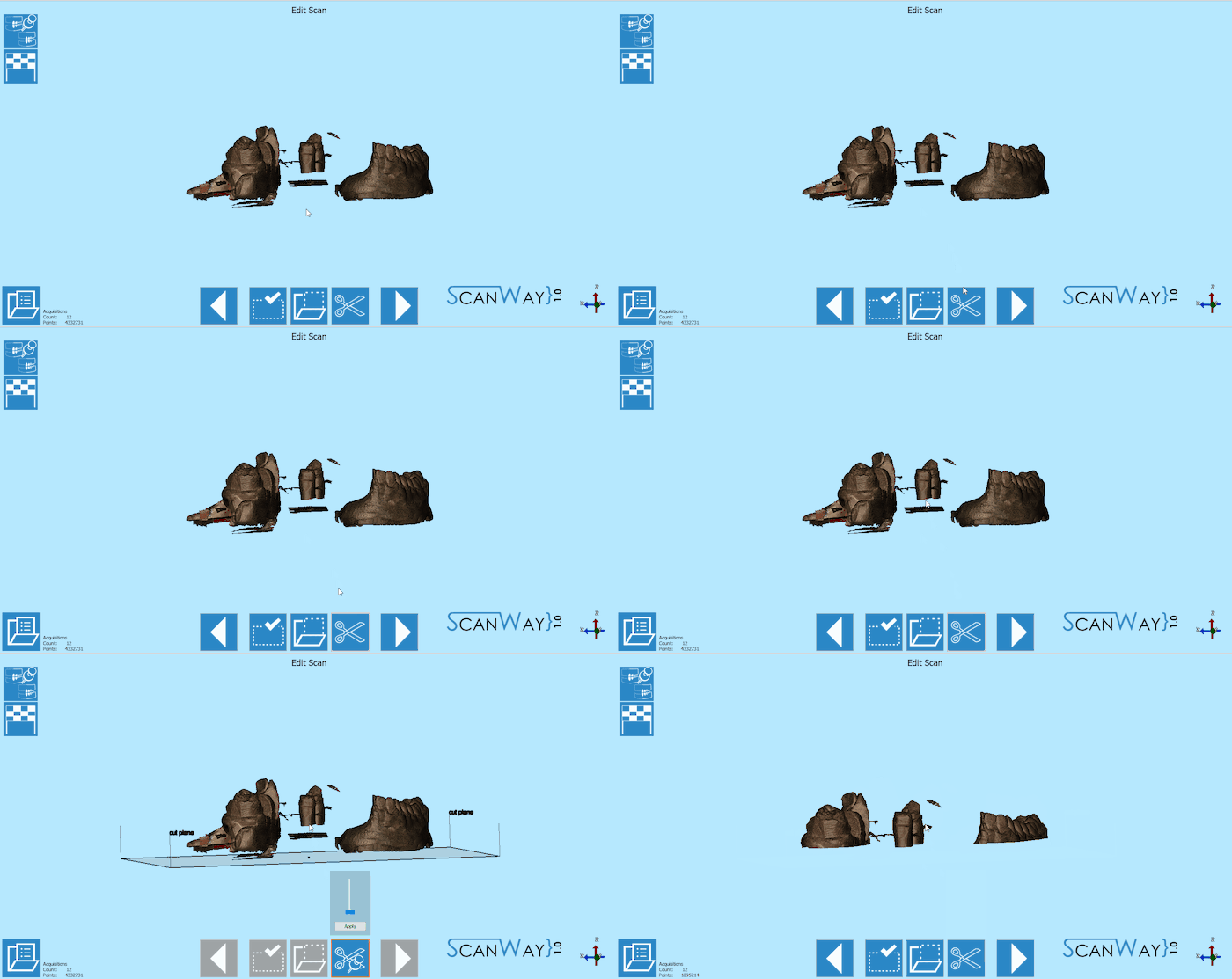
Edit
In this case, the image has been trimmed using the base cut tool and clicking on the apply button.
BE CAREFUL NOT TO TRIM TOO MUCH, AS TO DO SO THE SOFTWARE MIGHT HAVE ISSUES DURING THE AUTOMATIC ALIGNMENT
Click ![]() to access the alignment phase.
to access the alignment phase.
Alignment
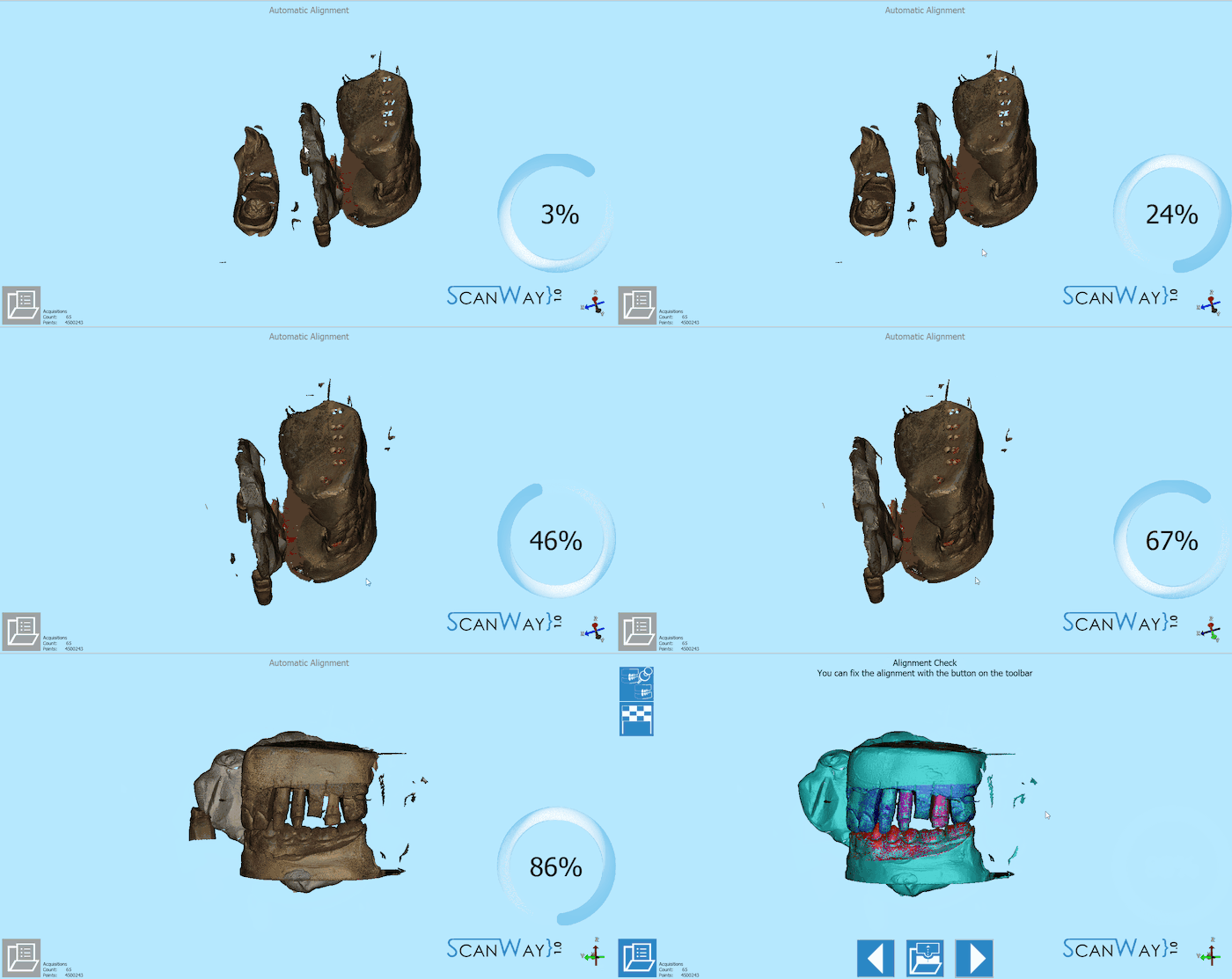
As for all scanned items, the software tries to align all the images to their reference. In this case the reference for all the scanned items is the articulator scan.
At the end of the alignment the results are shown. To learn more on the automatic alignment and the manual procedure visit our Alignment Interface page.
Click ![]() to access the last step of the wizard.
to access the last step of the wizard.
Step 3: Mesh Generation and Export
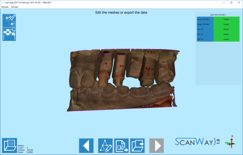
At this point the software immediately starts mesh generation. The meshes can be edited and exported individually or as a unique image. To learn more about mesh editing visit our Mesh Tools page.
Click on the Export Button ![]() to export to CAD.
to export to CAD.
If the project has been started from Exocad, the CAD will automatically open and the design can be started immediately. Otherwise the software will ask the user how to export the file.
