Example: Implants
Nesta página será seguido e explicado o assistente para escanear 1 modelo com 4 implantes e partes de gengiva de silicone.
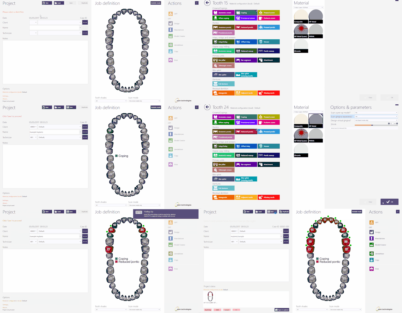
Para criar este projeto no Exocad, clique no ícone DentalDB na sua área de trabalho. O gerente do projeto será aberto.
Preencha as informações do projeto, o tipo de restauração que precisa ser projetado e os parâmetros extras. Para este tipo de projeto, certifique-se de que você selecionou o 'Tipo de Implante' e 'Gengiva Separada'
Para obter mais informações sobre como criar projetos no Exocad, visite a página específica no Exocad Wiki!
Aqui está a definição do projeto para o nosso projeto de demonstração:
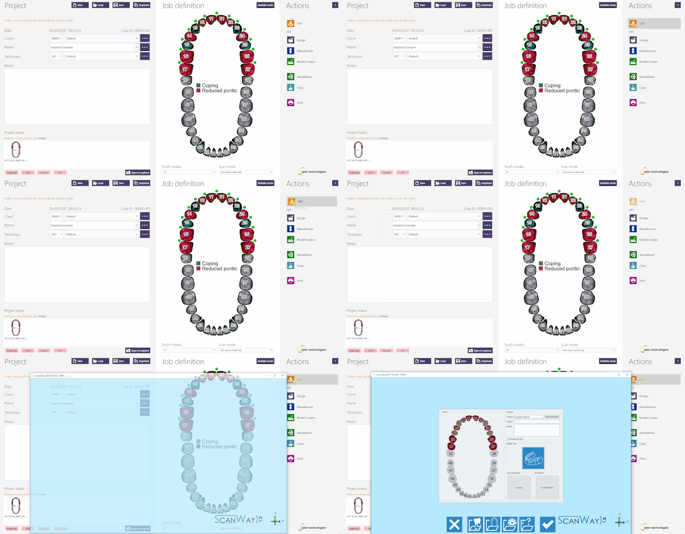
Uma vez definido o projeto, clique em 'OPT' na seção Ações para iniciar o software de escaneamento.
A primeira coisa que o software de escaneamento mostra é o projeto criado no Exocad, se o projeto estiver corretamente definido, clique no Botão Aceitar ![]() .
.
Contents
Definição do projeto a partir do ScanWay
Todos os projetos também podem ser definidos no software de escaneamento, independentemente do CAD que mais tarde será usado para projetar.
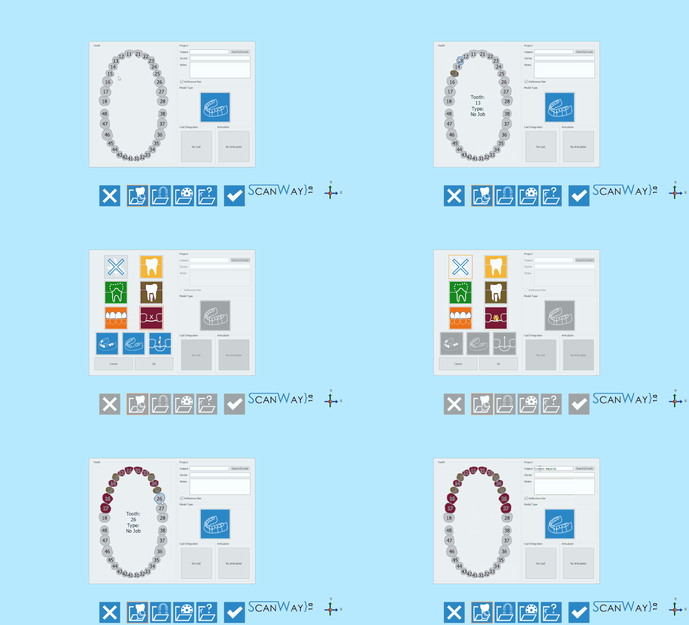
Inicie o software de digitalização clicando duas vezes no ícone do ScanWay na sua área de trabalho. A Página de boas-vindas será aberta; Para criar o projeto, clique no primeiro ícone.
Para obter informações detalhadas sobre como definir um projeto, visite a página específica: Criar um novo projeto.
Aqui está a definição do nosso projeto de demonstração:
Ambas as definições de projeto descritas levam ao mesmo assistente, que agora será seguido passo a passo.
Etapa 1: Modelo Superior
Uma vez que não existe um modelo oposto no projeto definido, o primeiro escaneamento necessário é o escaneamento do modelo superior, que será a referência para o posicionamento de todos os outros escaneamentos.
Este passo é dividido em duas etapas secundárias.
Etapa de Escaneamento
Coloque o modelo superior no suporte do modelo e clique no botão 'Botão de Escaneamento' ![]() .
.
AT THIS STAGE, ONLY THE STONE MODEL IS REQUIRED. REMEMBER TO TAKE OFF THE MODEL THE GINGIVA, MARKERS AND ANY OTHER ACCESSORY OBJECT
Once the scan is finished the result will be shown.
Click ![]() to access the edit step for the Upper model.
to access the edit step for the Upper model.
Edit Step
This step allows to edit the acquired image; for detailed information on all the available options in this step visit the Edit Tools page.
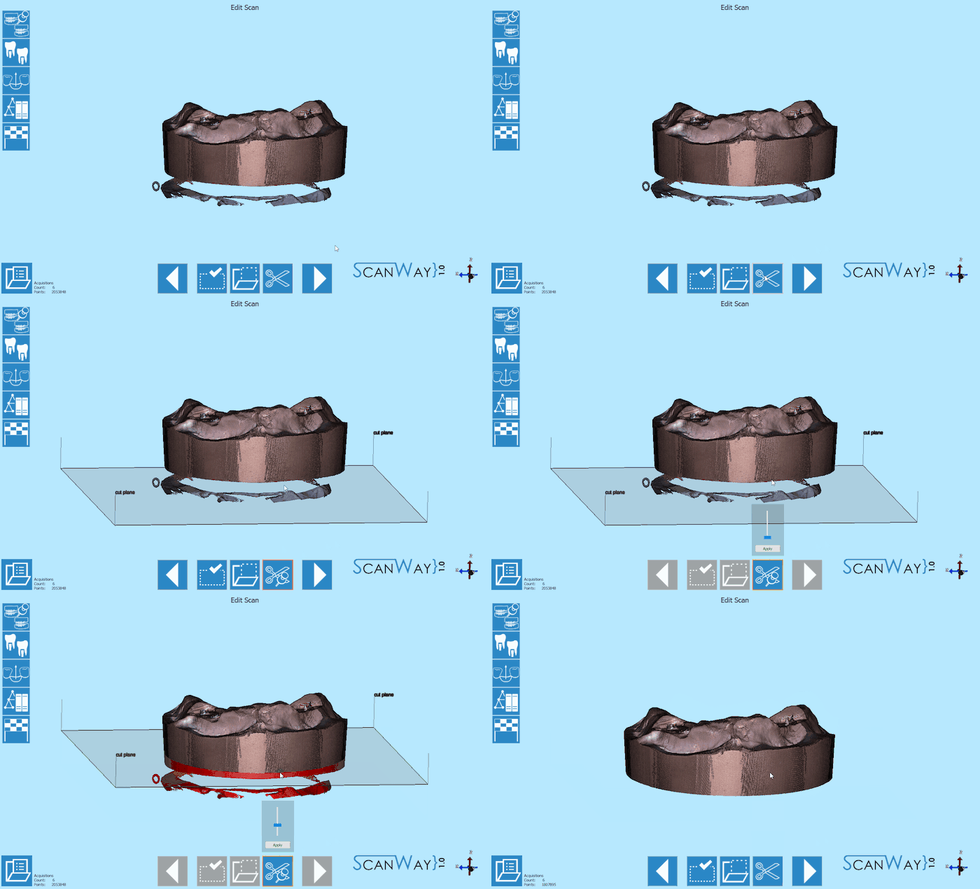
The image at this step can be both edited or trimmed. At this stage it is actually important not to edit too much the image or cutting big chunks of information, since it would make it more difficult for the software to calculate the automatic alignment of the object to its reference.
Here below an example on how to trim using the cut base tool and simply double-clicking on the image to remove the unwanted parts.
When you are satisfied with the result click ![]() to access the next wizard step.
to access the next wizard step.
Step 2: Markers
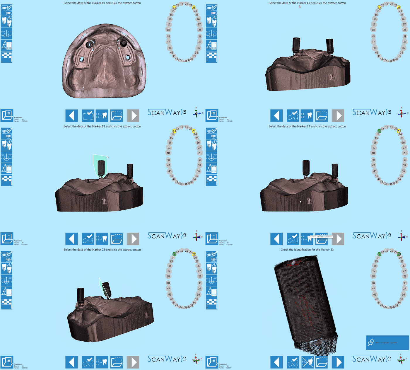
This step requires the user to scan the markers or scanbodies that will be used to mark the correct positioning of the geometry and screw channel of the implant in the CAD software.
The scan of the markers is divided in different steps.
Definition
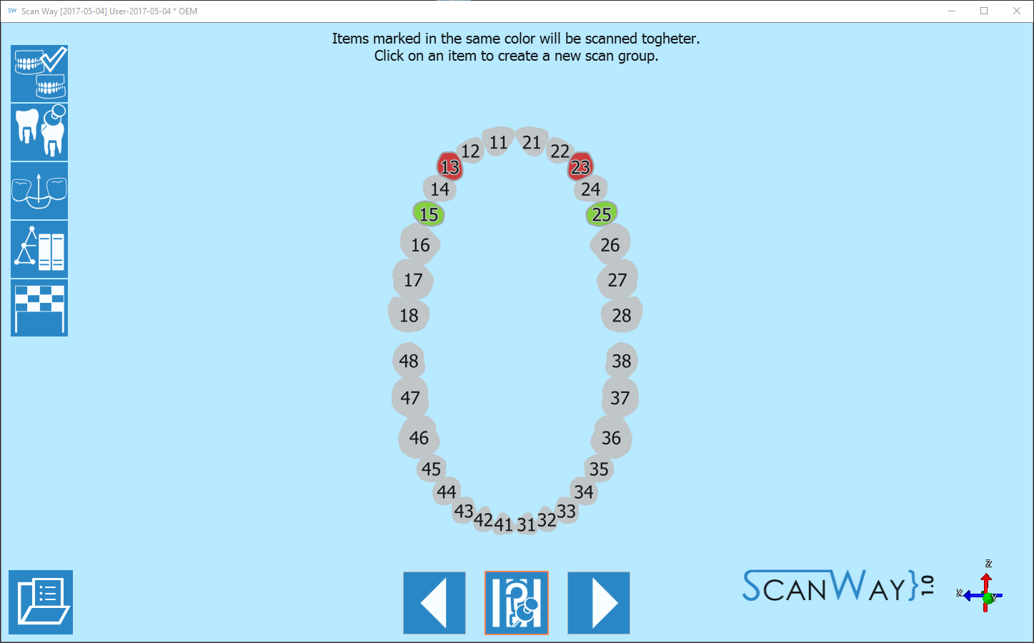
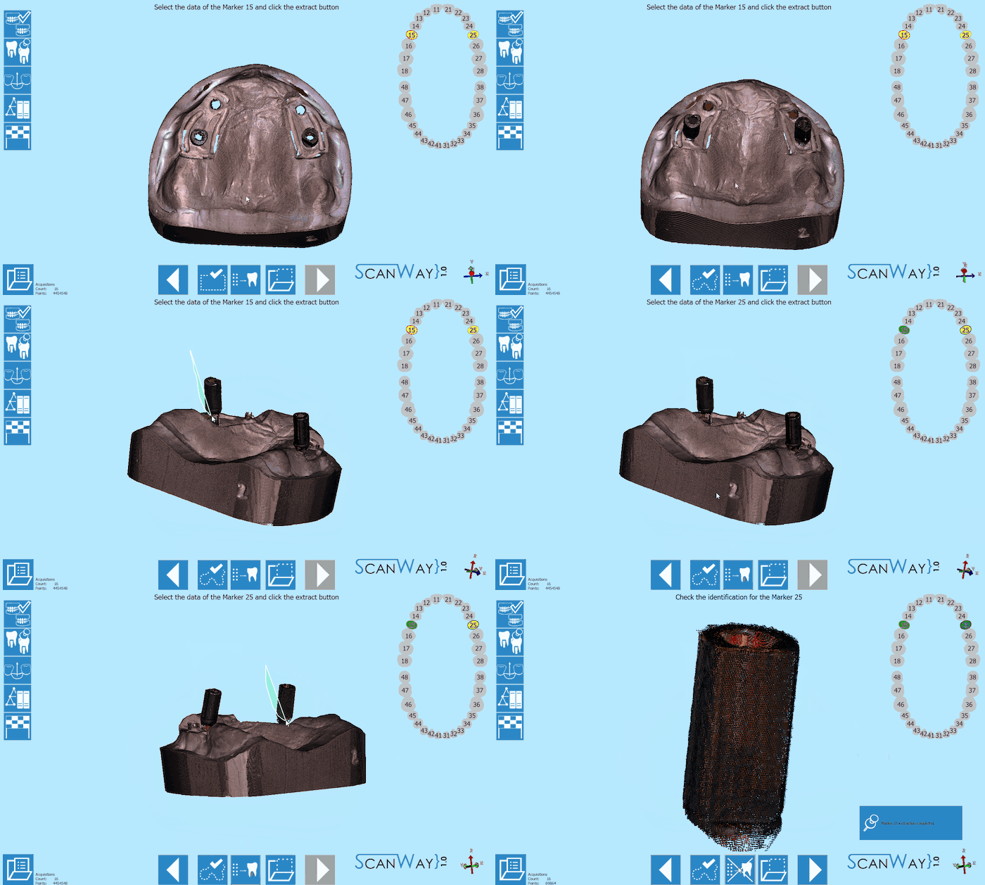
It is not necessary to have one marker for each implant on the model, since the markers can be scanned in different groups. To demonstrate this possibility, the 4 markers that need to be scanned for this project have been divided into two scanning groups, as follows:
Click ![]() to access the scan step for the first group.
to access the scan step for the first group.
First Group
- Scan
- Depending on the number of scan groups created, the software will propose one or more scanning steps.
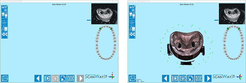
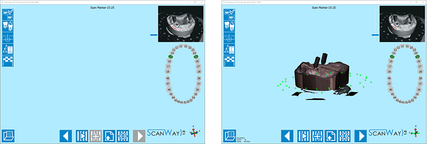
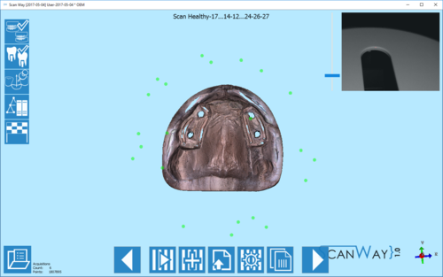
First, the software requires the user to insert the markers screwed on top of the model in the scanner and acquire the items of the first group.
As a reminder, it marks the items to be scanned together on the right of the window, under the live view.
Place the model with the selected markers on the model holder and click the Scan Button![]() . Once the scan is finished the result will be shown.
. Once the scan is finished the result will be shown.
Click ![]() to access the edit step.
to access the edit step.
- Edit
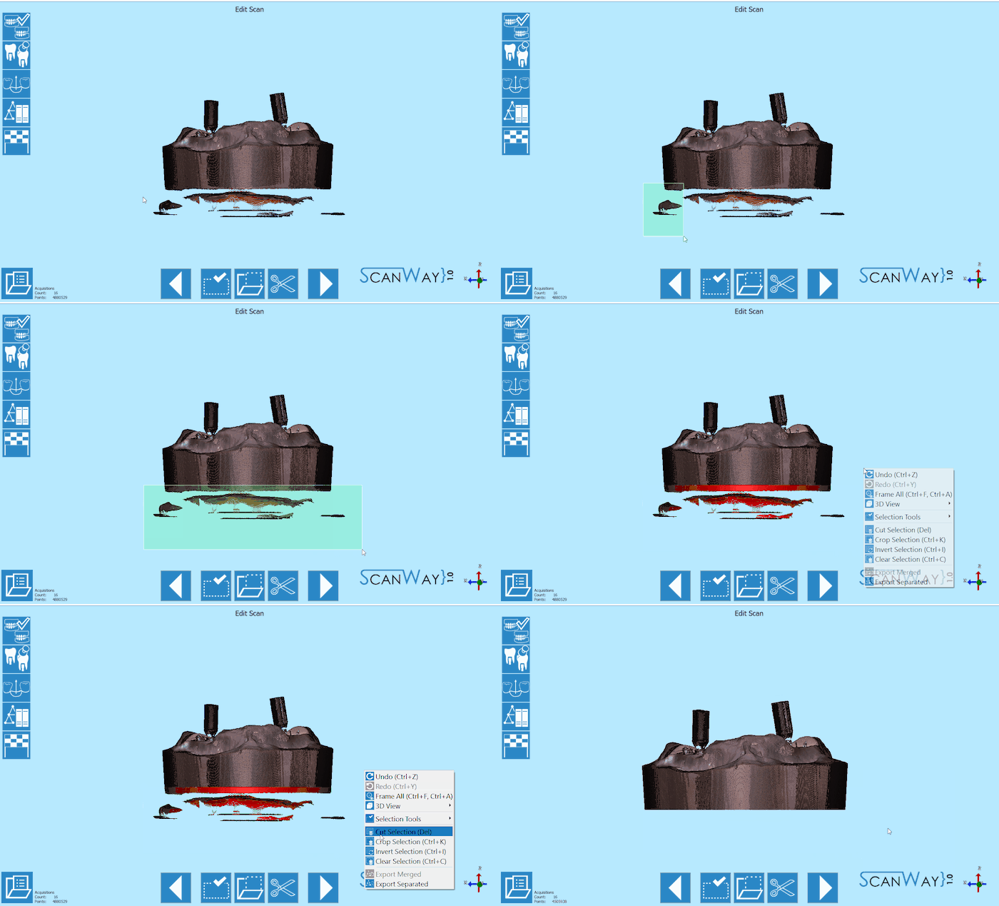
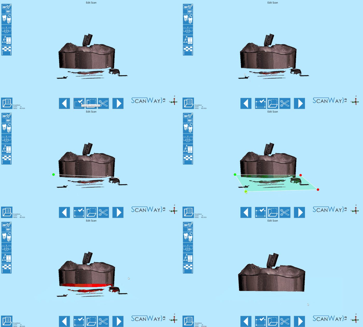
- Follows the edit step to clean or trim the image. This time the rectangular selection tool has been used and the cut action has been activated in the contextual menu.
Click ![]() to access the alignment step.
to access the alignment step.
- Alignment
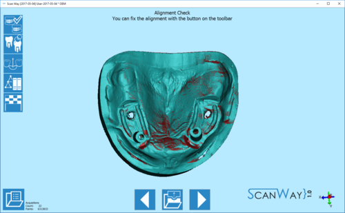
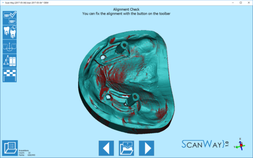
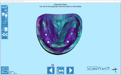
- The alignment for all scanned items is always automatic and it shows its results after the editing step.
To learn more on the automatic alignment and the manual procedure visit our Alignment Interface page.
- Marker Identification
- When a scan group has more than one item, the user will be asked to separate each marker from the others to correctly identify it.
To learn more on the identification of the dies visit the Scan Interface page.
Second group
- Scan
- Since in the project the markers have been divided into two groups, this is the last scan of the marker acquisition step.
As before, the software shows a reminder and marks the items to be scanned together on the right of the window, under the live view.
Place the model with the selected markers on the model holder and click the Scan Button![]() . Once the scan is finished the result will be shown.
. Once the scan is finished the result will be shown.
Click ![]() to access the edit step.
to access the edit step.
- Edit
- This image has been edited with the polygonal selection tool; the cut action has been activated in the contextual menu.
Click ![]() to access the alingment step.
to access the alingment step.
- Alignment
- The alignment for all scanned items is always automatic and it shows its results after the editing step.
To learn more on the automatic alignment and the manual procedure visit our Alignment Interface page.
- Marker Identification
- When a scan group has more than one item, the user will be asked to separate each marker from the others to correctly identify it.
To learn more on the identification of the dies visit the Scan Interface page.
Step 3: Gingiva
If in the project has been specified the presence of a silicon gingiva, that can be separated from the model, the software will ask the user to scan it on top of the reference model.
Also this step develops in different phases.
Scan Step
Place the upper model with the gingiva on the model holder and click the Scan Button![]() .
.
Once the scan is finished the result will be shown.
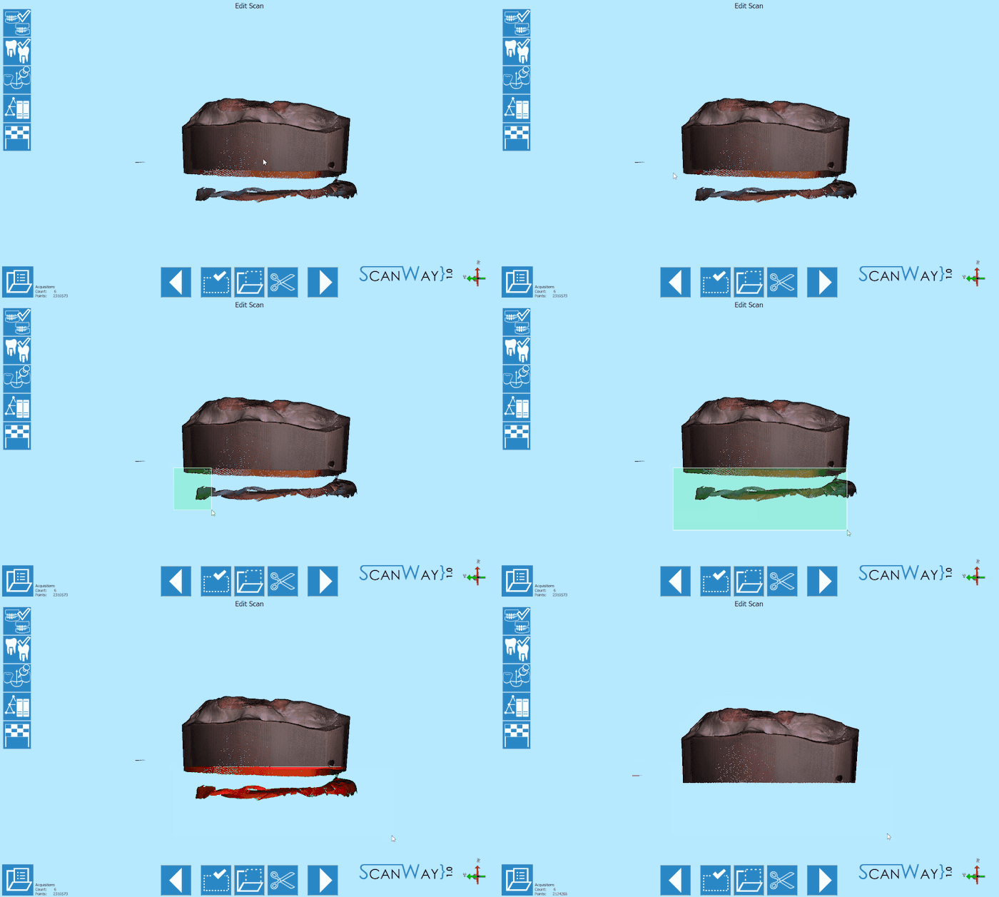
Edit Step
This item has been trimmed using the rectangular selection tool; the selected part has been deleted by pushing the DELETE (DEL) button on the keybord.
Automatic Alignment
As for the other items, the image of the gingiva aligns automatically to its reference (the upper model). The model part that matches the reference will then be removed automatically to keep only the actual gingiva part in mesh format.
Step 4: Healthy and Pontics
At this stage the project has been scanned, unless the user wants to rescan the healthy and pontics. In this case, since there are no healthy teeth there is no need to rescan.
Click ![]() to continue.
to continue.
The software will then propose a further edit step to allow the user to modify the healthy image. Proceed in the edit step as previously explained.
Step 5: Marker Alignment
To serve their purpose, the markers need to be aligned to an implant library: a virtual, geometric, accurate representation of the scanbody that has been screwed to the stone analog to mark its position.
The alingment to the library can be perfomed either in the scanning software or in Exocad. Since the market of libraries and scanbodies is so diverse, it is possible that some libraries will not work in our system.
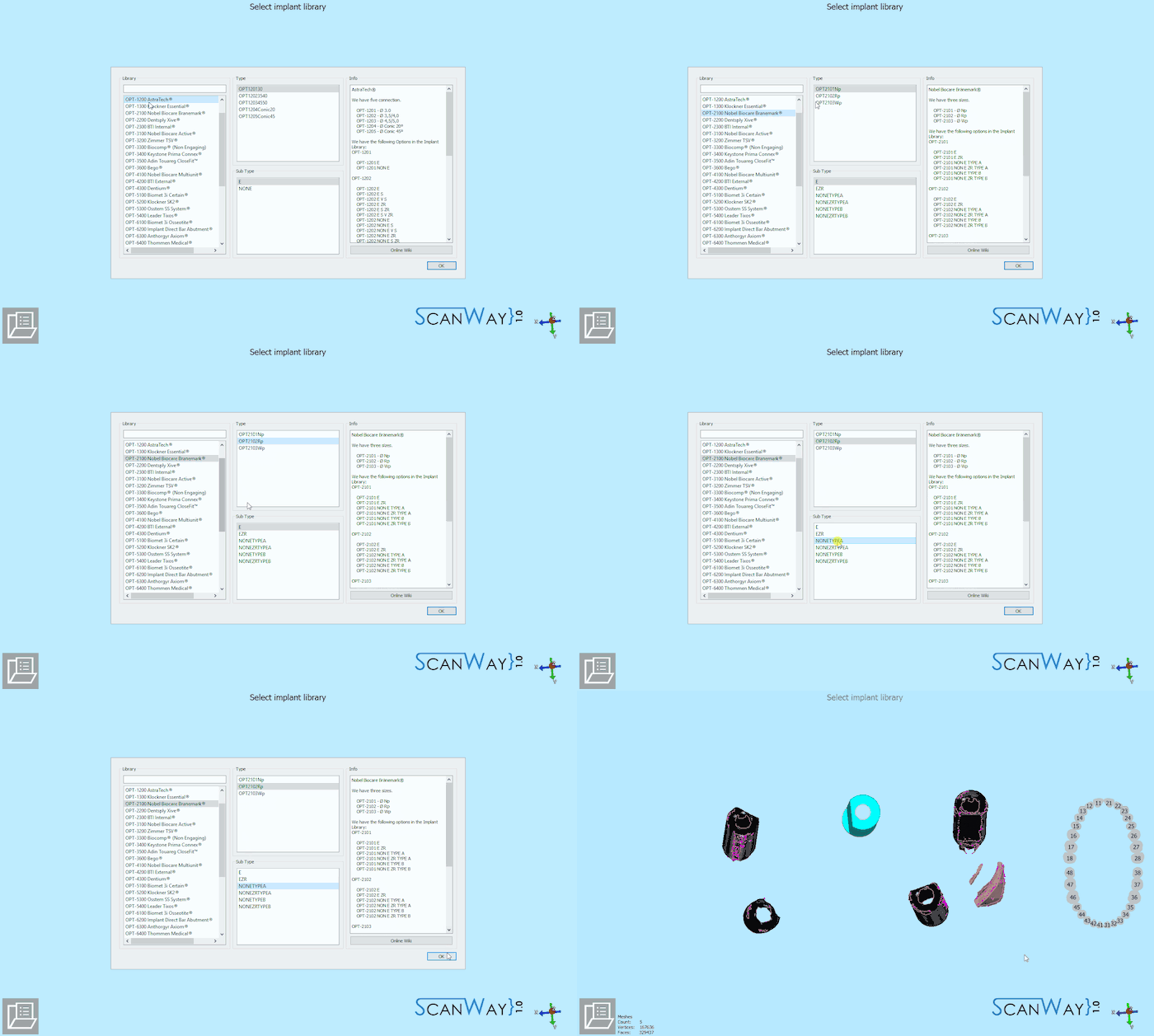
Here below the library selection performed for our demo case:
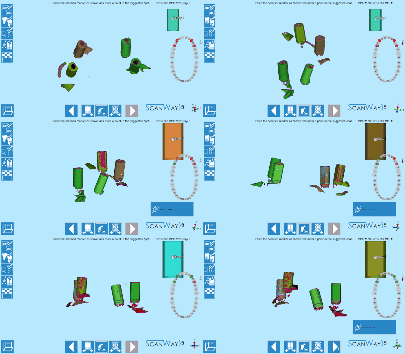
Immediately after, the user will be asked to align the STL of the Marker to the scanned items:
To learn more on how to select a library and align the scanbodies to it, visit the section Marker alignment of the page Alignment Interface.
Step 6: Mesh Generation and Export
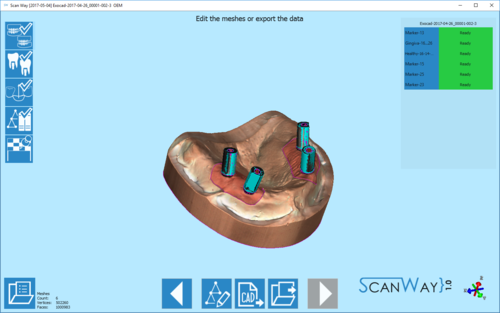
At this point the software immediately starts mesh generation. The meshes can be edited and exported individually or as a unique image. To learn more about mesh editing visit our Mesh Tools page.
Click on the Export Button ![]() to export to CAD.
to export to CAD.
If the project has been started from Exocad, the CAD will automatically open and the design can be started immediately. Otherwise the software will ask the user how to export the file.
