Example: Multidie
In questa pagina è mostrata e spiegata la procedura guidata da seguire per scansionare Monconi di diversi pazienti sullo stesso supporto multidie.
Contents
Definizione del progetto in Exocad
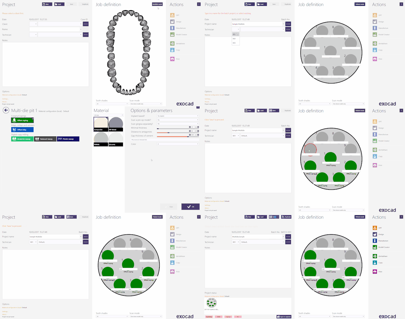
Per creare questo progetto in Exocad, cliccare sull'icona DentalDB sul desktop, aprendo così il Gestore Progetti. Fare click su Multi Die per aprire il pannello di definizione del progetto.
Per maggiori informazioni su come creare progetti in Exocad, visitare la pagina Exocad Wiki!
Di seguito la definizione di un progetto esempio:
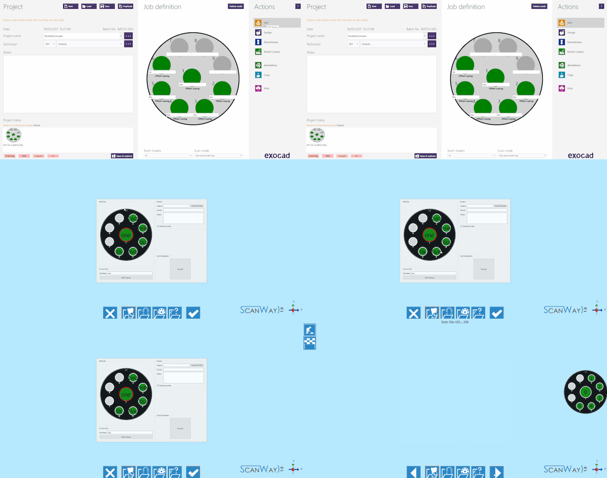
Una volta che il progetto è stato definito è sufficiente cliccare su OPT nella sezione Azioni per avviare il software di scansione.
Il software mostrerà come prima cosa il progetto creato in Exocad. Se il progetto è corretto, cliccare il pulsante Accetta ![]() .
.
Definizione del progetto da ScanWay
Tutti i progetti possono essere definiti nel software di scansione stesso, indipendentemente dal tipo di CAD che verrà poi utilizzato per la modellazione.
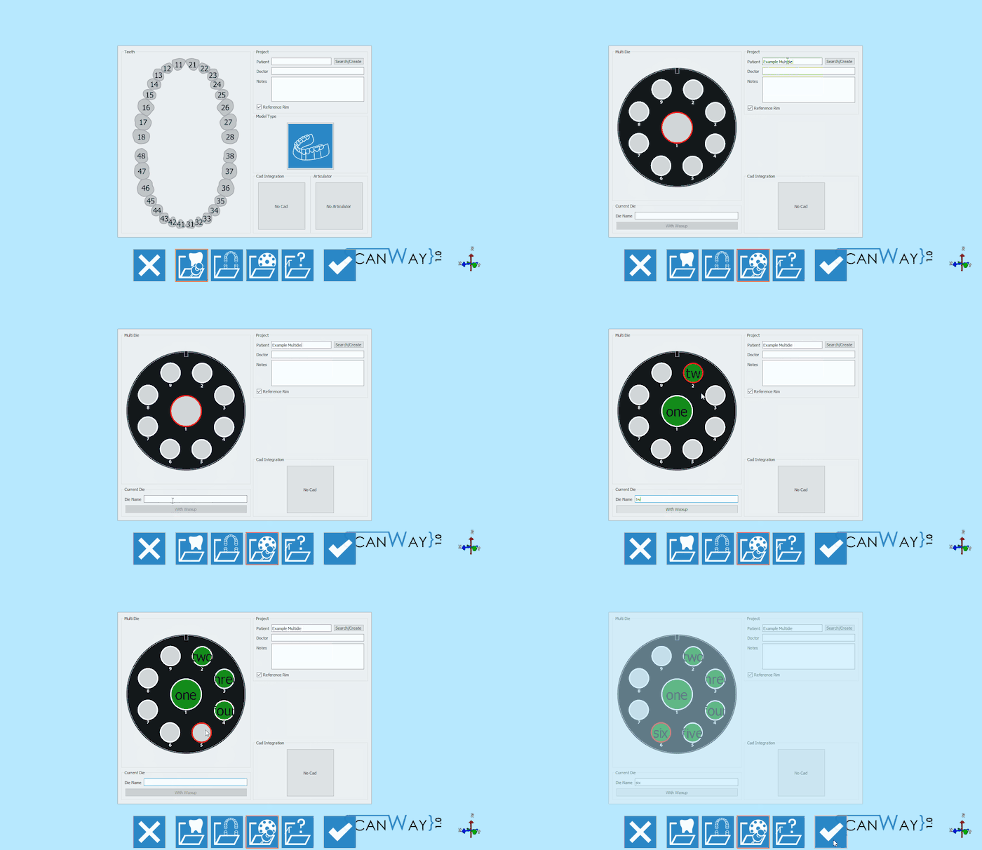
Avviare il software facendo doppio click sull'icona ScanWay sul desktop. Si aprirà la Pagina di Benvenuto; per creare il progetto cliccare sulla prima icona.
Per informazioni più dettagliate su come definire un progetto, visitare la pagina: Creare un Nuovo Progetto.
Di seguito la definizione del nostro progetto esempio:
Le definizioni di progetto sopra descritte portano entrambe ad avviare la medesima procedura guidata, che è composta dai passaggi seguenti.
Passaggio 1: Scansione Multidie
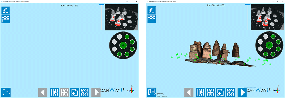
Questo è l'unico passaggio di scansione in questo tipo di progetto. Come al solito, questo passaggio di scansione si suddivide in sotto-passaggi.
Scan Step
Place the dies on the multidie plate as prompted by the scanner and click the Scan Button![]() . Once the scan is finished the result will be shown.
. Once the scan is finished the result will be shown.
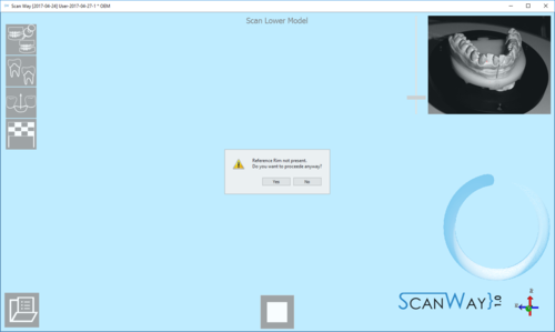
This scan has been performed with the Reference Rim. Everytime the user launches a scan for models, dies or markers, if the software recognises that the reference rim has not been used the following message shows.
The user can therefore decide whether to cancel the scan, put the reference rim on the model holder and start a new scan, or to scan without using the reference rim. For information on the reference rim visit the Accessories page.
Click ![]() to access the second part of the step.
to access the second part of the step.
Edit Step
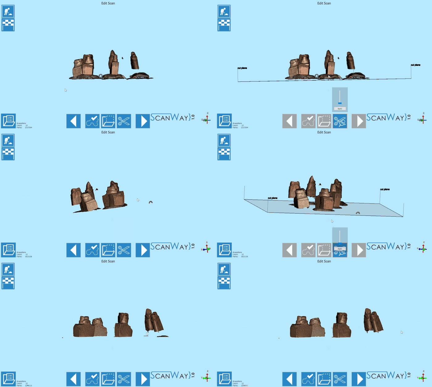
This step allows to edit the aquired image; for detailed information on all the available options in this step visit the Edit Tools page.
The image at this step can be both edited or trimmed. In this case, various tools have been used.
When you are satisfied with the result click ![]() to access the next wizard step.
to access the next wizard step.
Step 6: Mesh Generation and Export
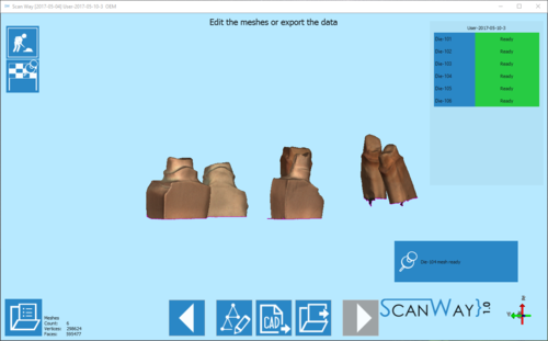
At this point the software immediately starts mesh generation. The meshes can be edited and exported individually or as a unique image. To learn more about mesh editing visit our Mesh Tools page.
Click on the Export Button ![]() to export to CAD.
to export to CAD.
If the project has been started from Exocad, the CAD will automatically open and the design can be started immediately. Otherwise the software will ask the user how to export the file.
