Example: Multidie
Nesta página será seguido e explicado o assistente para o escaneamento dos munhões de diferentes pacientes na mesma placa multimunhão.
Contents
Definição do projeto a partir de Exocad
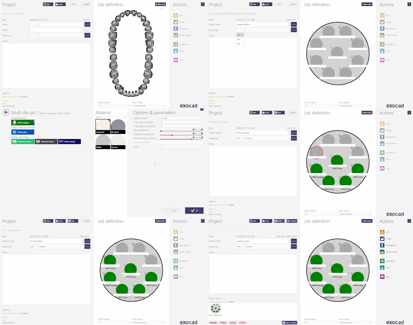
Para criar este projeto no Exocad, clique no ícone DentalDB na sua área de trabalho. O gerente do projeto será aberto. Clique em 'Multi Munhão' , para abrir o painel de definição do projeto.
Para obter mais informações sobre como criar projetos no Exocad, visite a página específica no Exocad Wiki!
Aqui está a definição do projeto para o nosso projeto de demonstração:
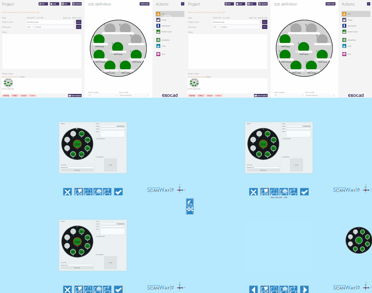
Uma vez definido o projeto, clique em 'OPT' na seção Ações para iniciar o software de escaneamento.
A primeira coisa que o software de escaneamento mostra é o projeto criado no Exocad, se o projeto estiver corretamente definido, clique no Botão Aceitar ![]() .
.
Definição do projeto a partir do ScanWay
Todos os projetos também podem ser definidos no software de escaneamento, independentemente do CAD que mais tarde será usado para projetar.
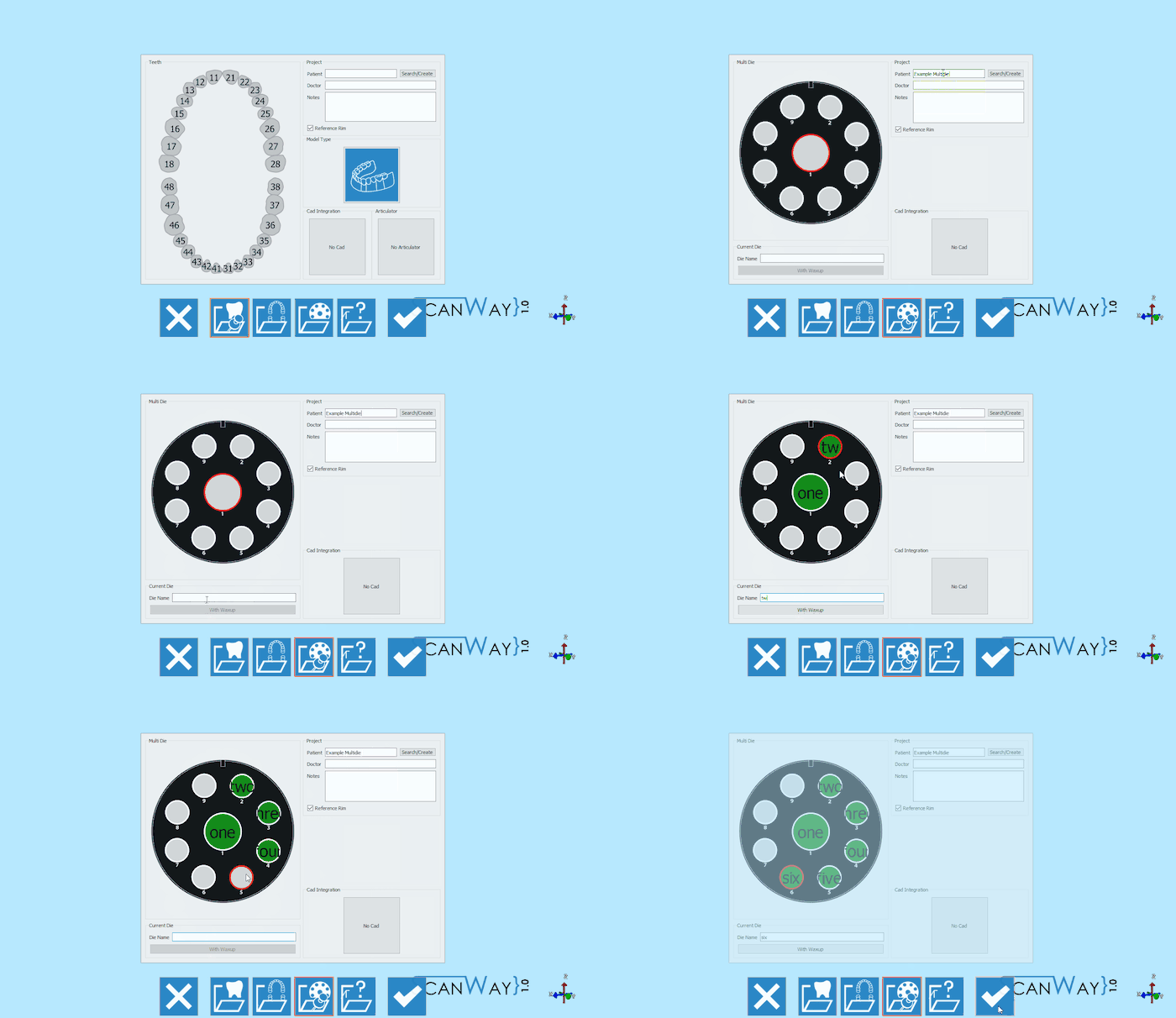
Launch the scanning software double-clicking on the ScanWay icon on your desktop. The Welcome Page will open; to create the project click on the first icon.
Para obter informações detalhadas sobre como definir um projeto, visite a página específica: Criar um Novo Projeto.
Aqui está a definição do nosso projeto de demonstração:
Ambas as definições de projeto descritas levam ao mesmo assistente, que agora será seguido passo a passo.
Step 1: Multidie Scan
This is the only scan step for this kind of project. As usual, this scan steps is divided into substeps.
Scan Step
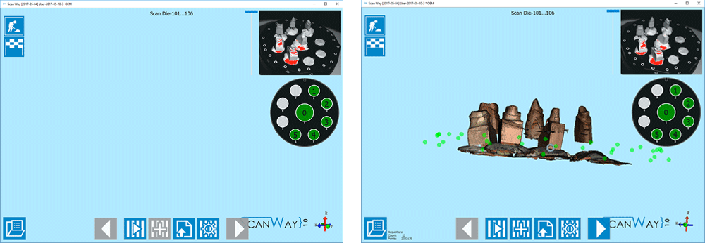
Place the dies on the multidie plate as prompted by the scanner and click the Scan Button![]() . Once the scan is finished the result will be shown.
. Once the scan is finished the result will be shown.
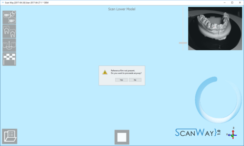
This scan has been performed with the Reference Rim. Everytime the user launches a scan for models, dies or markers, if the software recognises that the reference rim has not been used the following message shows.
The user can therefore decide whether to cancel the scan, put the reference rim on the model holder and start a new scan, or to scan without using the reference rim. For information on the reference rim visit the Accessories page.
Click ![]() to access the second part of the step.
to access the second part of the step.
Edit Step
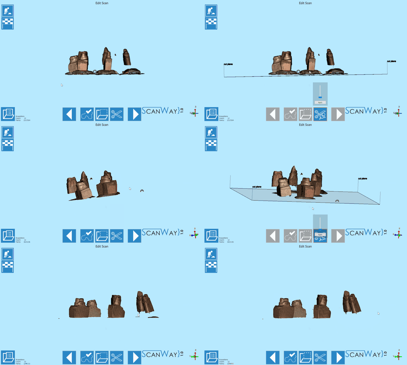
This step allows to edit the aquired image; for detailed information on all the available options in this step visit the Edit Tools page.
The image at this step can be both edited or trimmed. In this case, various tools have been used.
When you are satisfied with the result click ![]() to access the next wizard step.
to access the next wizard step.
Step 6: Mesh Generation and Export
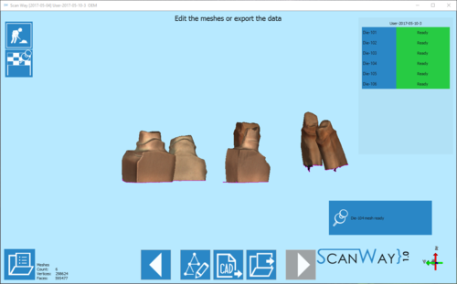
At this point the software immediately starts mesh generation. The meshes can be edited and exported individually or as a unique image. To learn more about mesh editing visit our Mesh Tools page.
Click on the Export Button ![]() to export to CAD.
to export to CAD.
If the project has been started from Exocad, the CAD will automatically open and the design can be started immediately. Otherwise the software will ask the user how to export the file.
