Difference between revisions of "ExamplesFullJ/pt-br"
(Created page with "O segundo passo de qualquer projeto que tenha sido configurado para ter ambas as arcadas, é o Escaneamento Modelo Inferior. Todas as etapas, exceto para o articulador, inclue...") |
(Created page with "===Etapa Escaneamento===") |
||
| Line 45: | Line 45: | ||
O segundo passo de qualquer projeto que tenha sido configurado para ter ambas as arcadas, é o Escaneamento Modelo Inferior. Todas as etapas, exceto para o articulador, incluem duas sub-etapas: o escaneamento real e a edição da imagem adquirida. | O segundo passo de qualquer projeto que tenha sido configurado para ter ambas as arcadas, é o Escaneamento Modelo Inferior. Todas as etapas, exceto para o articulador, incluem duas sub-etapas: o escaneamento real e a edição da imagem adquirida. | ||
| − | === | + | ===Etapa Escaneamento=== |
Place the lower model on the model holder and click the '''Scan Button'''{{Inline button|scanAction.png}}. Once the scan is finished the result will be shown. | Place the lower model on the model holder and click the '''Scan Button'''{{Inline button|scanAction.png}}. Once the scan is finished the result will be shown. | ||
Revision as of 14:05, 4 July 2017
Nesta página será seguido e explicado o assistente para o escaneamento de 2 modelos completos em oclusão.
Contents
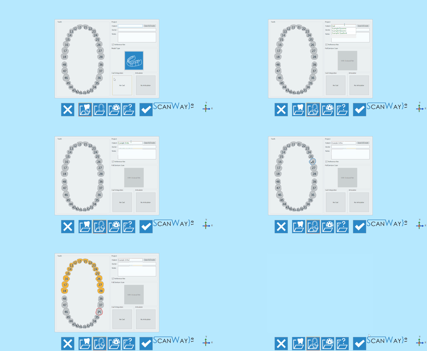
Definição do Projeto
Launch the scanning software double-clicking on the ScanWay icon on your desktop. The Welcome Page will open; to create the project click on the first icon.
Para obter informações detalhadas sobre como definir um projeto, visite a página específica: Criar um novo projeto.
Aqui está a definição do nosso projeto de demonstração:
Etapa 1: Escaneamento Articulador
O primeiro passo de qualquer projeto que tenha sido configurado para ter ambas as arcadas, é o Escaneamento do Articulador.
'Para o escaneamento do Articulador, não é necessariamente necessário que um Articulador precise ser escaneado; o escaneamento necessário é a aquisição da oclusão usando o articulador em seu suporte específico ou colocando os dois modelos em oclusão no suporte modelo
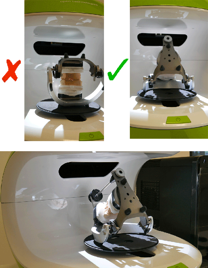
Se o usuário precisar escanear um articulador, sugerimos inclinar-lo para trás, para poder obter o máximo de informações possível. Esta é apenas uma sugestão, pois nem todos os articuladores podem ser inclinados.
Na visão ao vivo da interface de escaneamento, você pode realmente ver que, se o articulador estiver reto, será difícil adquirir a oclusão corretamente
Por outro lado, como mencionado anteriormente, também é possível escanear os dois modelos em oclusão no suporte do modelo normal mantido junto com bandas de borracha ou cera, se necessário.
Uma vez que os objetos foram colocados no scanner (tanto o articulador como os modelos um em cima do outro), o escaneamento pode ser iniciado com o 'Botão de Escaneamento' x25px. Uma vez concluído o escaneamento, o resultado será mostrado.
Para obter mais informações sobre as outras funções disponíveis, verifique a página Escan Interface.
Clique em x25px para acessar a segunda etapa do assistente.
Etapa 2: Modelo Inferior
O segundo passo de qualquer projeto que tenha sido configurado para ter ambas as arcadas, é o Escaneamento Modelo Inferior. Todas as etapas, exceto para o articulador, incluem duas sub-etapas: o escaneamento real e a edição da imagem adquirida.
Etapa Escaneamento
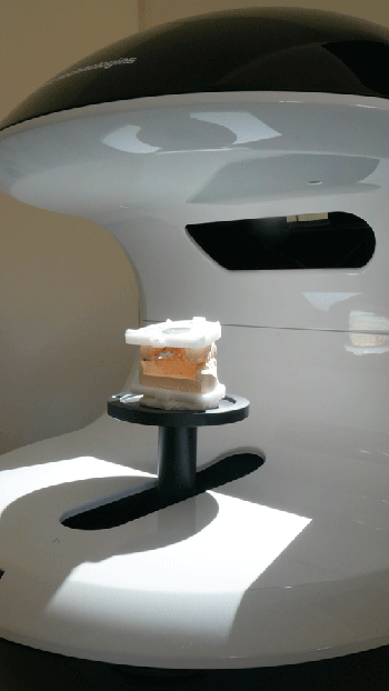
Place the lower model on the model holder and click the Scan Button![]() . Once the scan is finished the result will be shown.
. Once the scan is finished the result will be shown.
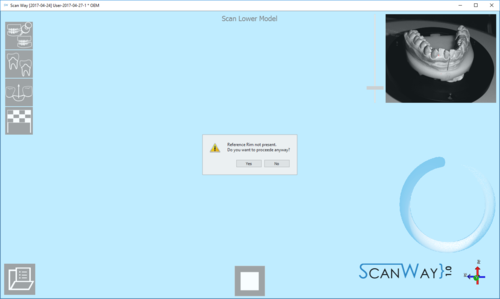
This scan has been performed with the Reference Rim. Everytime the user launches a scan for models, dies or markers, if the software recognises that the reference rim has not been used the following message shows.
The user can therefore decide whether to cancel the scan, put the reference rim on the model holder and start a new scan, or to scan without using the reference rim. For information on the reference rim visit the Accessories page.
Click ![]() to access the second part of the Lower model step.
to access the second part of the Lower model step.
Edit Step
This step allows to edit the acquired image; for detailed information on all the available options in this step visit the Edit Tools page.
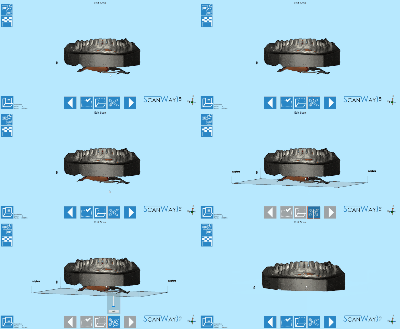
The image at this step can be both edited or trimmed. At this stage it is actually important not to edit too much the image or cutting big chunks of information, since it would make it more difficult for the software to calculate the automatic alignment of the object to its reference.
In this case, to trim the object, the base cut tool has been used and accepted by double clicking on the model.
When you are satisfied with the result click ![]() to access the next wizard step.
to access the next wizard step.
Step 3: Upper Model
The upper model Scan, like the lower model, requires the user to undergo two steps.
Scan Step
Place the upper model on the model holder and click the Scan Button![]() . Once the scan is finished the result will be shown.
. Once the scan is finished the result will be shown.
As before, if the reference rim is not placed on the model holder, the software will show the relevant message.
Click ![]() to access the edit step for the Upper model.
to access the edit step for the Upper model.
Edit Step
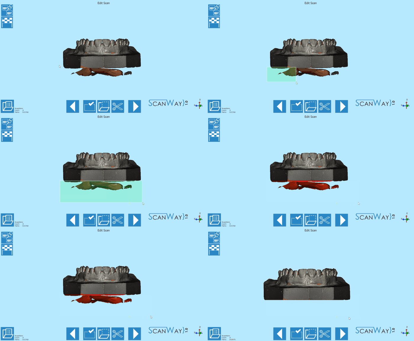
The upper model can still be edited as shown for the lower model. This time, we will edit the image using a selection tool and cutting with the delete button on the keybord.
When you are satisfied with the result click ![]() to access the next wizard step.
to access the next wizard step.
Save and Align
Immediately after having pushed the ![]() button, the software saves and tries to align automatically the scanned items to their reference.
button, the software saves and tries to align automatically the scanned items to their reference.
To learn more on the automatic alignment and the manual procedure visit our Alignment Interface page.
Step 6: Mesh Generation and Export
At this point the software immediately starts mesh generation. The meshes can be edited and exported individually or as a unique image. To learn more about mesh editing visit our Mesh Tools page.
Click on the Export Button ![]() to export to CAD and select the folder to save the STL files.
to export to CAD and select the folder to save the STL files.
