Example: Dynamic Articulator Module
In questa pagina è mostrata e spiegata la procedura guidata da seguire per scansionare 2 modelli in occlusione con 3 monconi (2 superiori e 1 inferiore) utilizzando il Modulo Articolazione Dinamica di Open Technologies.
Il Modulo Articolazione Dinamica permette all'utente di trasferire l'occlusione realizzata in laboratorio con un articolatore fisico nel suo equivalente virtuale in Exocad. Gli articolatori supportati in Exocad, per i quali possiamo fornire posizionamento esatto, sono Artex, Protarevo Kavo, Sam, Bioart A7 e Denar by Whipmix.
Quando si abilita il Modulo Articolazione Dinamica, si fornisce all'utente un set di 6 Piattelli Splitcast ed un Oggetto di Calibrazione. Vedere Accessori- Modulo Articolazione Dinamica.
Prima di usare questo Modulo per la prima volta è necessario calibrare gli assi dello scanner per lavorare in linea con la simulazione dell'occlusione. Per imparare a calibrare, visitare la pagina Calibrare lo scanner.
QUESTO E UN MODULO DI LICENZA AGGIUNTIVO DI OPEN TECHNOLOGIES: RICHIEDI AL TUO DISTRIBUTORE COME OTTENERLO!!
Contents
Definizione del progetto in Exocad
Per creare questo progetto in Exocad, cliccare sull'icona DentalDB sul desktop, aprendo così il Gestore Progetti.
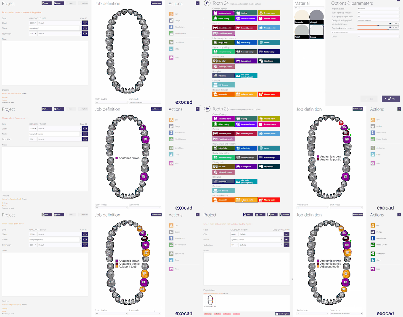
Inserire le informazioni del progetto, il tipo di ricostruzione che dovrà essere modellata e i parametri aggiuntivi. Per questo tipo di progetto assicurarsi che la Modalità Scansione sia impostata su uno degli Articolatori virtuali di Exocad disponibili; scegliere tra:
- Due modelli nell'Articolatore A per Artex
- Due modelli nell'Articolatore S per Sam o Adesso
- Due modelli nell'Articolatore P per Protarevo- Kavo
- Due modelli nell'Articolatore B per Bioart's A7
- Due modelli nell'Articolatore D per Denar by Whipmix
Per maggiori informazioni su come creare progetti in Exocad, visitare la pagina Exocad Wiki!!
Di seguito la definizione di un progetto esempio; abbiamo utilizzato l'Articolatore Protarevo di Kavo:
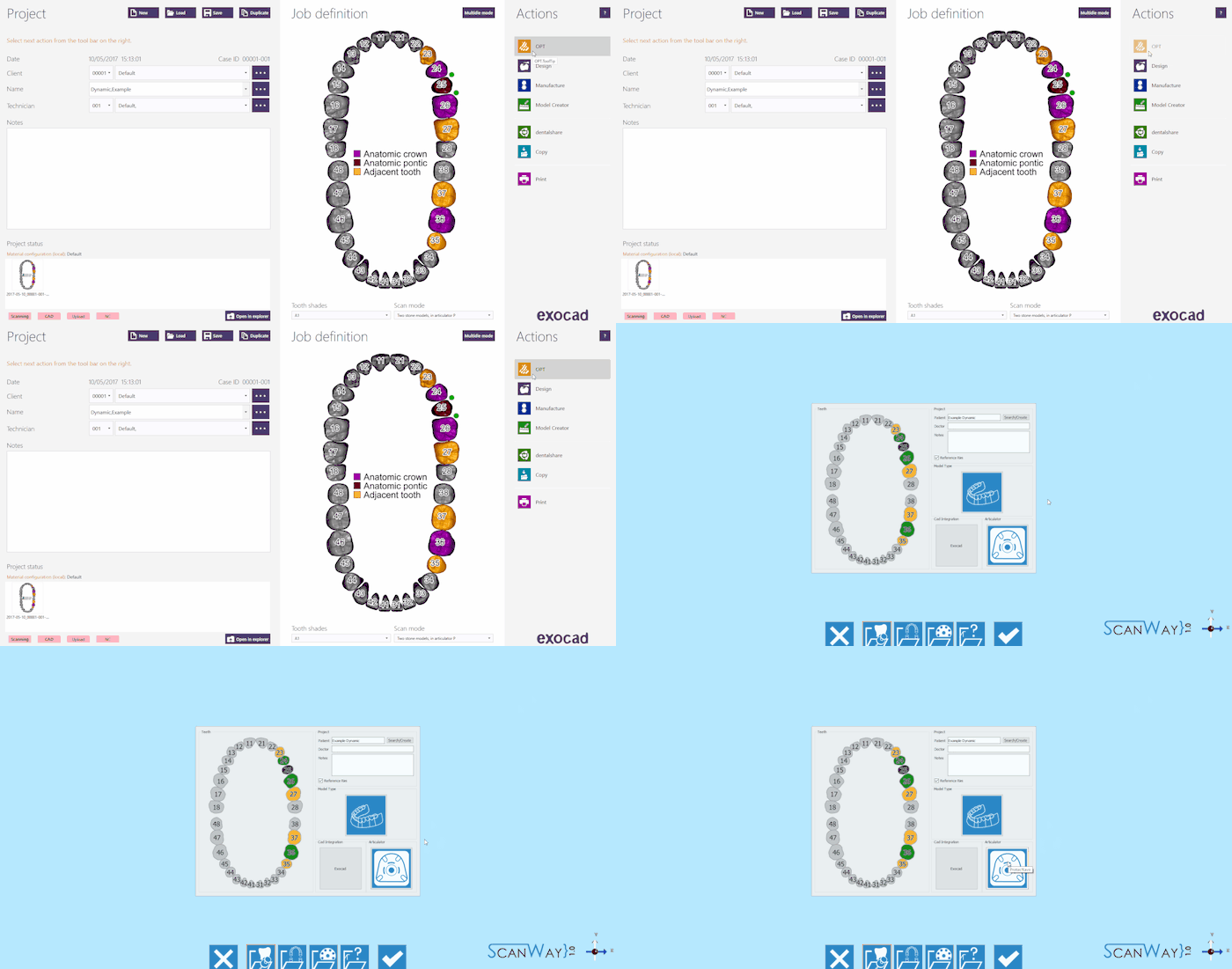
Una volta che il progetto è stato definito è sufficiente cliccare su OPT nella sezione Azioni per avviare il software di scansione.
La prima cosa mostrata dal software di scansione è il progetto creato in Exocad. Verificare che la selezione dell'articolatore sia corretta, e fare click sul Pulsante Accetta ![]() .
.
Definizione del progetto da ScanWay
Tutti i progetti possono essere definiti nel software di scansione stesso, indipendentemente dal tipo di CAD che verrà poi utilizzato per la modellazione.
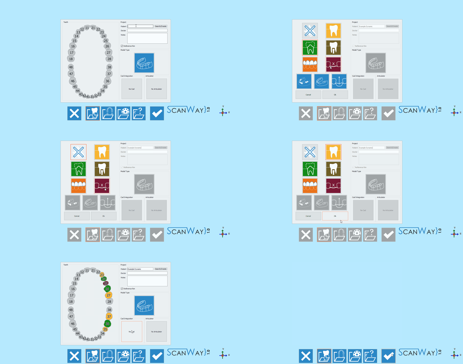
Avviare il software facendo doppio click sull'icona ScanWay sul desktop. Si aprirà la Pagina di Benvenuto; per creare il progetto cliccare sulla prima icona.
Per informazioni più dettagliate su come definire un progetto, visitare la pagina: Creare un Nuovo Progetto.
Per questo progetto, porre particolare attenzione alla selezione dell'articolatore. Se l'articolatore viene definito in maniera errata, l'articolazione virtuale non sarà realistica ed utilizzabile.
Inoltre, ricordarsi di impostare Exocad come software CAD, poiché questo modulo è specificamente creato per lavorare con l'Articolatore Virtuale di Exocad.
Di seguito la definizione del nostro progetto esempio:
Le definizioni di progetto sopra descritte portano entrambe ad avviare la medesima procedura guidata, che è composta dai passaggi seguenti.
Passaggio 1: Scansione Articolatore
Il primo passaggio di ogni progetto impostato con entrambe le arcate è la Scansione Articolatore.
In questo caso specifico bisogna scansionare l'Articolatore. L'articolatore da scansionare deve corrispondere a quello selezionato nella definizione del progetto.
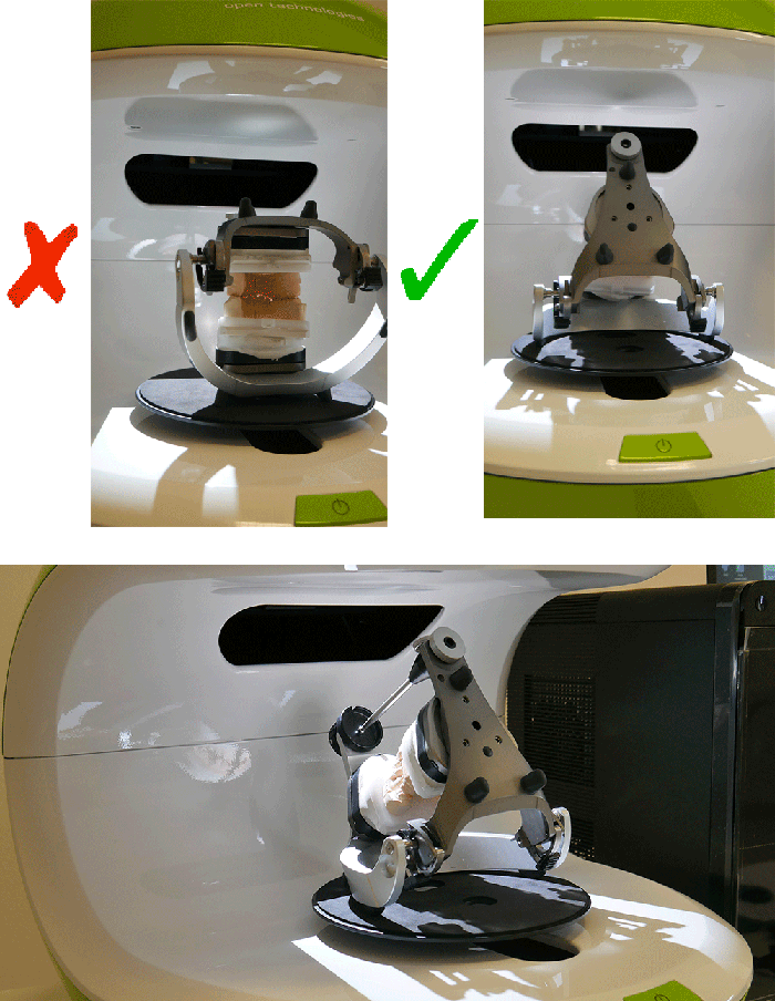
Consigliamo di scansionare l'articolatore inclinandolo all'indietro, per ottenere quanti più dati possibili. Questo suggerimento potrebbe non applicarsi a tutti gli articolatori dato che alcuni non possono essere inclinati.
Nella sezione Vista Live dell'interfaccia di scansione è possibile notare in effetti che se l'articolatore rimane dritto risulta difficile acquisire i dati in modo completo.
Una volta che i modelli sono stati inseriti nello scanner (con l'articolatore o uno sopra l'altro, in occlusione), è possibile avviare l'acquisizione con il Pulsante Scansiona![]() . A scansione terminata, i risultati verranno mostrati sullo schermo.
. A scansione terminata, i risultati verranno mostrati sullo schermo.
Per ulteriori informazioni sulle altre funzioni disponibili, visita la pagina Interfaccia di Scansione.
Cliccare ![]() per accedere al secondo passaggio della modalità guidata.
per accedere al secondo passaggio della modalità guidata.
Passaggio 2: Arcata inferiore
Il secondo passaggio di ogni progetto con entrambe le arcate è la scansione del modello inferiore. Tutti i passaggi, escluso quello della scansione articolatore, prevedono due sotto-passaggi: la scansione e la modifica dell'immagine acquisita.
Scan Step
Place the lower model on the splitcast base matching the selected articulator; for our demo case we used the Protarevo- Kavo Splitcast base.
Click the Scan Button![]() . Once the scan is finished the result will be shown.
. Once the scan is finished the result will be shown.
Click ![]() to access the second part of the Lower model step.
to access the second part of the Lower model step.
Edit Step
This step allows to edit the acquired image; for detailed information on all the available options in this step visit the Edit Tools page.
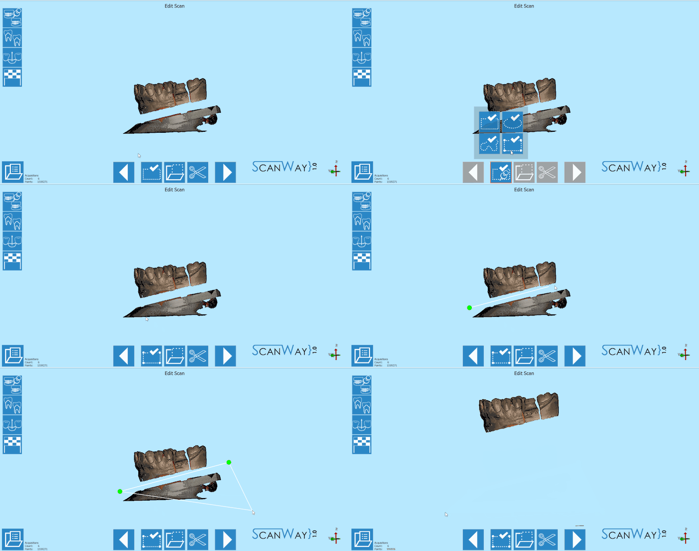
The image at this step can be both edited or trimmed. At this stage it is actually important not to edit too much the image or cutting big chunks of information, since it would make it more difficult for the software to calculate the automatic alignment of the object to its reference.
In this particular case, since the model is mounted in the articulator, it's not scanned on a perfectly horizontal plane, so to trim it faster we used the polygonal selection tool.
When you are satisfied with the result click ![]() to access the next wizard step.
to access the next wizard step.
Step 3: Upper Model
The upper model Scan, like the lower model, requires the user to undergo two steps.
Scan Step
Place the upper model on the splitcast base matching the selected articulator and click the Scan Button![]() . Once the scan is finished the result will be shown.
. Once the scan is finished the result will be shown.
Click ![]() to access the edit step for the Upper model.
to access the edit step for the Upper model.
Edit Step
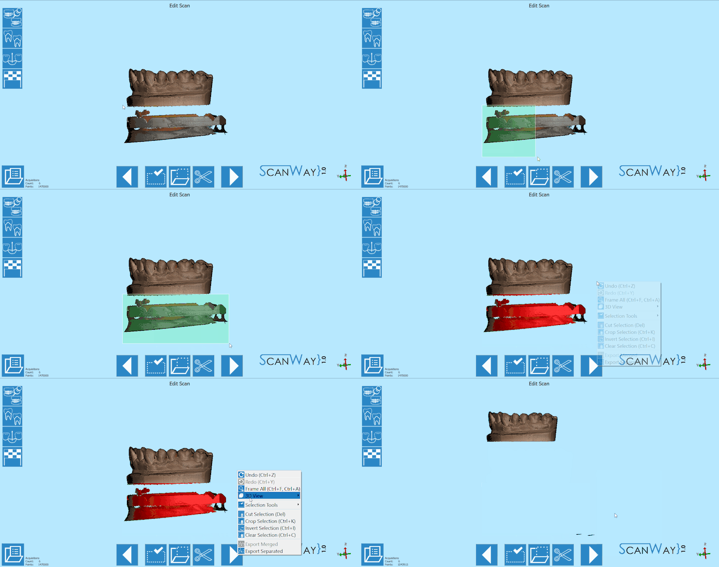
The upper model can still be edited as shown for the lower model. This time, we will edit the image using a different selection tool.
Step 4: Dies Scan
The steps necessary to successfully scan the dies vary depending on the scanning method that the user chooses to apply: the use of the multidie plate or the custom set-up.
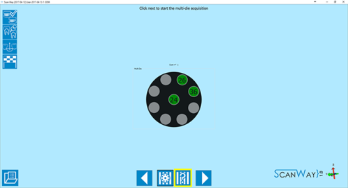
With Multidie
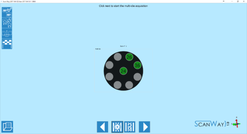
This method is applied by default by the software. It implies that the user will put the dies on the multidie plate in the position shown by the software, which will make each die immediately recognisable and cut the steps of the wizard.
- Definition
- As mentioned, the position of the dies in the multidie plate is pre-established by the software.
The multidie order is based on the Universal tooth numbering, starting from the last element of the first quadrant and following in a clock-wise order. Therefore the die that needs to be placed in the central element will always be the one closest to the last element of the first quadrant.
If there are more than 9 dies, a second definition step will be shown.
Click ![]() to access the multidie scan step.
to access the multidie scan step.
- Scan
- The multidie scan interface is similar to the other steps we just explained, except for the multidie reference that is kept as a reminder on the right side of the window, under the live view.
To proceed click the Scan Button . Once the scan is finished the result will be shown.
Click ![]() to access the edit step for the multidie scan.
to access the edit step for the multidie scan.
- Edit
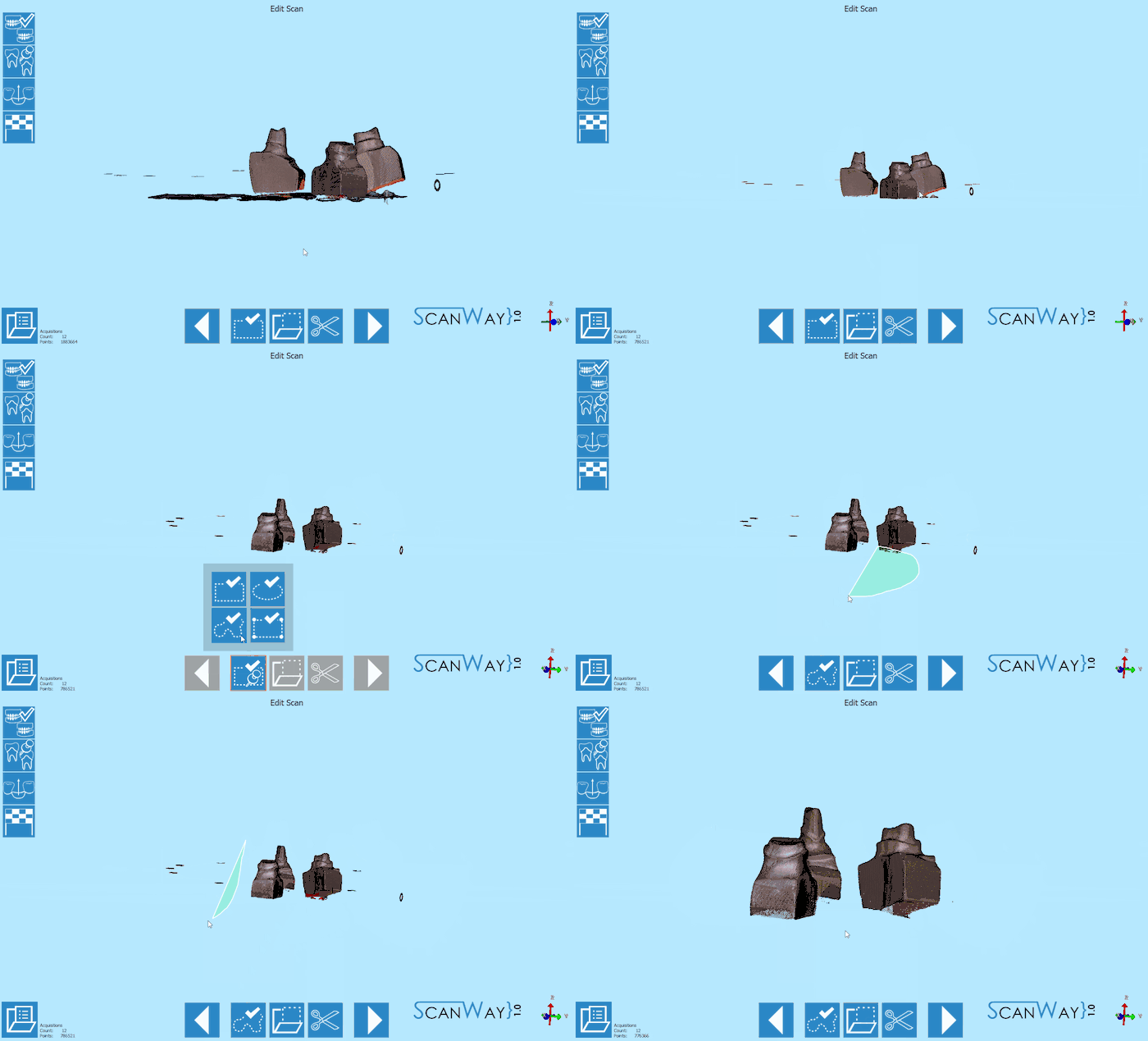
- The edit step offers the same tools we saw in previous steps. In this case, more than one tool may need to be applied.
When you are satisfied with the result click ![]() to access the next wizard step.
to access the next wizard step.
- Alignment
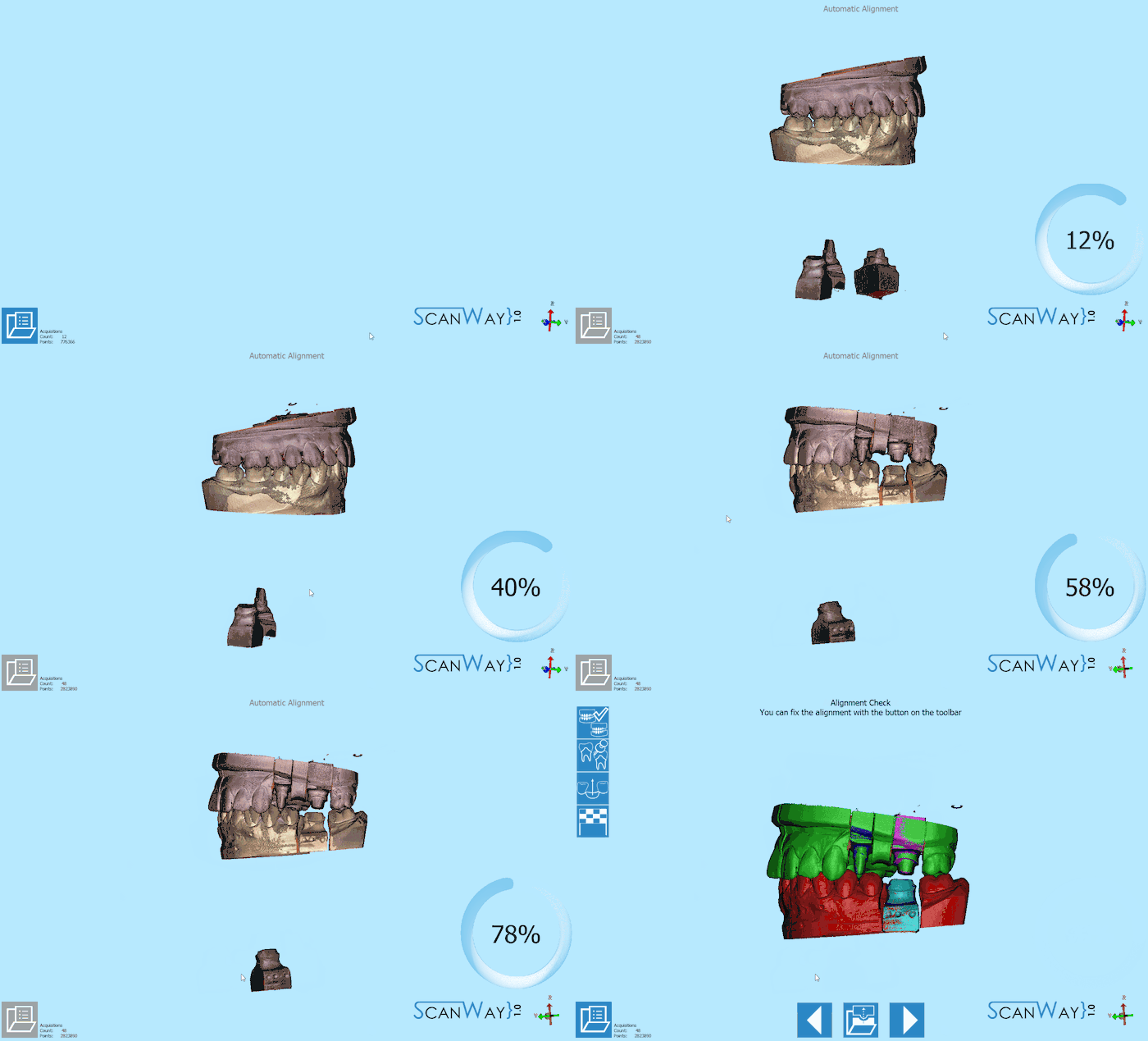
- After being edited the dies get aligned to their references. The result is then showed on the monitor. To learn how to change, fix or redo the alignment check the Alignment Interface page.
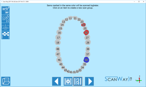
Custom Set-Up (Without Multidie)
The user can also decide to scan the dies in a custom order, for instance if he needs to scan the dies on the model base. To access the custom set- up definition, click on the ![]() icon when the software presents the multidie definition.
icon when the software presents the multidie definition.
- Definition
- The software proposes by default a unique scan group which means that, if not defined otherwise, the software will ask the user to scan all the stumps together. In this case I have created a second scan group, to divide the scan of the upper dies from the scan of the lower dies. Click
 to access the scan steps.
- Scan
- Depending on the number of scan groups created, the software will propose one or more scanning steps.
First, the software requires the user to insert the dies in the scanner and acquire the items of the first group.
As a reminder, it marks the items to be scanned together on the right of the window, under the live view.
Then it will ask the user to insert the item selected for the second group. Since the second scan is an individual die, there will be no reminder on the right. Click ![]() to continue.
to continue.
- Dies Identification
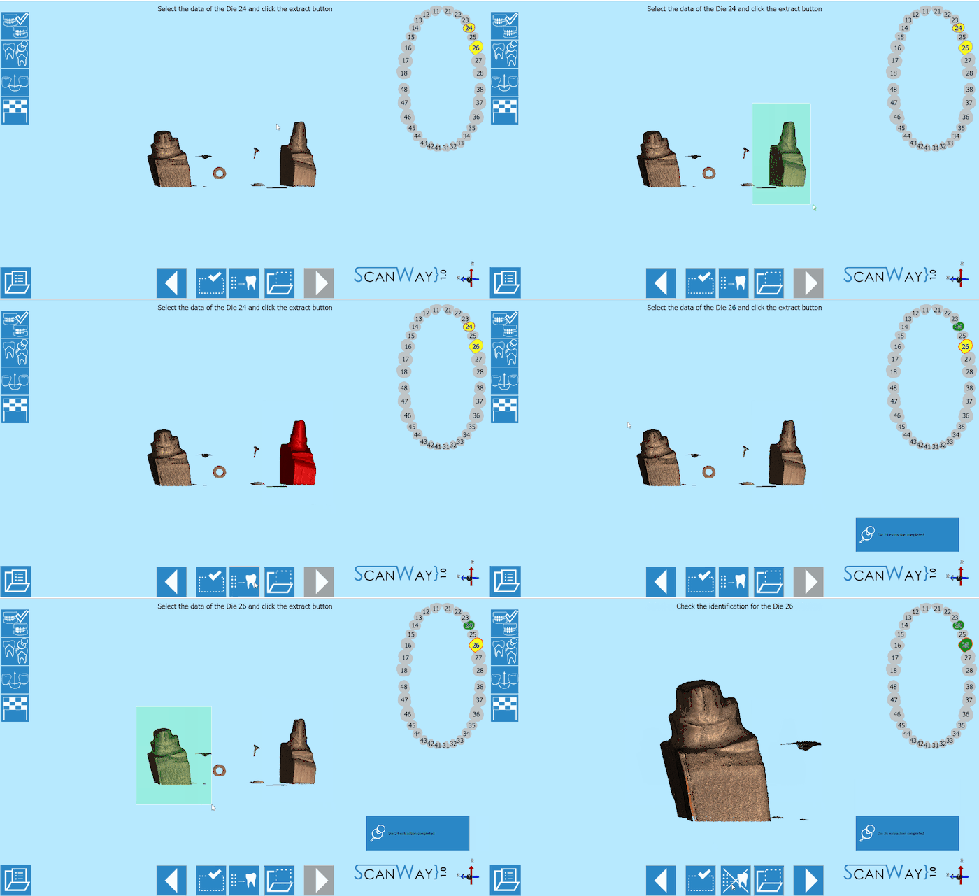
- When a scan group has more than one item, the user will be asked to separate each die from the others to correctly identify it.
This step occurs in between the scanning steps. To learn more on the identification of the dies visit the Scan Interface page. Click to continue.
- Edit
- If the scan group is formed by one individual die, there will be no identification step. Instead, the edit step will be presented. Click
 to continue.
- Alignment
- After being edited or identified the dies get aligned to their references. The result is then showed on the monitor. To learn how to change, fix or redo the alignment check the Alignment Interface page.
Step 5: Healthy and Pontics
At this stage the project has been scanned, unless the user wants to rescan the healthy and pontics. This step is infact a result of the scan of the scanned reference model, trimmed to exclude the parts that have been scanned individually (in this case, the dies). It sometimes happens that in the first model scan, the contact points on the healthy are not correctly recognised, which would require the user to rescan the model. Otherwise, just click ![]() to continue.
to continue.
The software will then propose a further edit step to allow the user to modify the healthy image. Proceed in the edit step as previously explained.
Step 6: Mesh Generation and Export
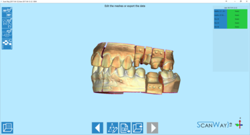
At this point the software immediately starts mesh generation. The meshes can be edited and exported individually or as a unique image. To learn more about mesh editing visit our Mesh Tools page.
Click on the Export Button ![]() to export to CAD.
to export to CAD.
If the project has been started from Exocad, the CAD will automatically open and the design can be started immediately. Otherwise the software will ask the user how to export the file.
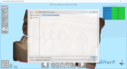
Since Exocad has been selected in ScanWay's project definition, the software will ask the user to find the folder containing the DentalProject file for this job.
